OK here we go. Let me preface this with two things because in the past, when I have posted pictures of work that I have done, I've received a few nasty comments about lousy soldering, poor organization etc. I started this hobby in late 2020 and there's no question some of my restorations have looked amateurish. I'm 64 years old now with shaky hands. Despite this, most of my electrical work is solid and reliable. I by no means try to pass myself off as an experienced electronics restorer. Constructive advice is always welcome, in fact, it's desired but I'm sure some here will not participate or lose interest when the journey reveals stupid mistakes or poor technique. So be it. I desperately want to get this TV working but it was altered significantly by previous work over decades and I've done my best to attempt to problem solve. With all this in mind, I'll make my second point.
I started work on this TV a couple of years ago when I had a significantly different approach to restoration. Today I use the standard method of trying to baseline the TV through a slow power up on original parts. Once that's done, I do methodical replacement of components where I think the failure points are and then check function. But a few years ago, I shotgun recapped my restorations and I had a reliable bookkeeping method but I did create errors that were then difficult to run down. That's the method I used and describes the current state of this TV. I have some rudimentary function in the relay/rectifier section but then I start to hit walls.
I had the great fortune to run across this on eBay and snatched it up.
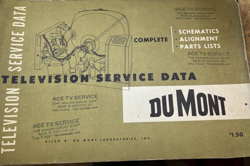
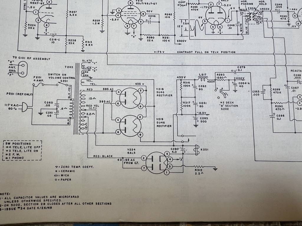
This was a great acquisition because of the quality of the available resources. I can't read the Sams schematic. The copy quality is poor and the print is microscopic. The Riders service data is much more useful and I've been using it as an adjunct to the publication above. Below is the Dumont Service Manual schematic for the RA-103

Below is the detail of the section I have had success with. The relay works and the circuit closes powering the entire TV
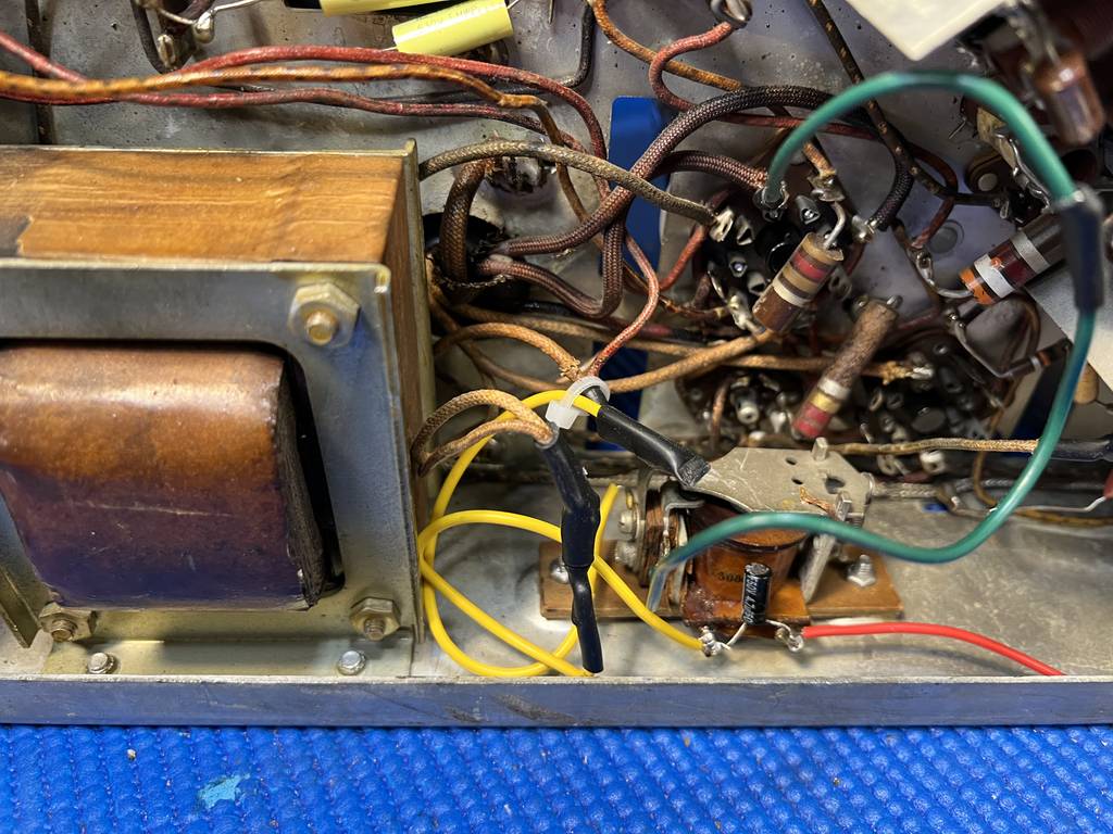
OK, here are some pictures of the chassis. I did relocate the focus pot and I am in the middle of wiring it up. It's mounted on the side of the rear of the chassis under the HV cage. The wiring in the rectifier section is a mess and I will clean it up. I tested function on 4 relays so there was a lot of extension wiring to test it unmounted. Oh hell...I'll just post them all! Go ahead, let me have it!


Relocation of the focus pot, not yet wired up. Should I use Tom's suggestion of a shaft extender

I'll move it back to the original position.
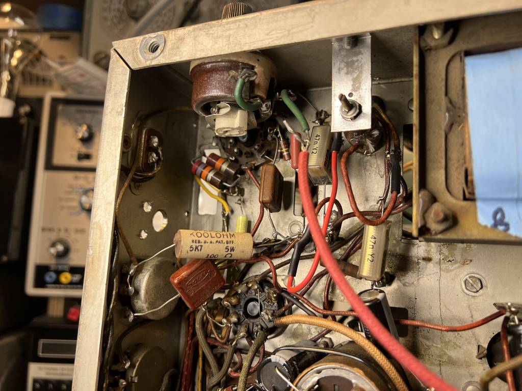
The original focus pot still in place but out of circuit. The 750ohm resistor hanging off the chassis is something I put in circuit to test TV function in the absence of a working 1K focus rheostat. It's no longer in circuit.
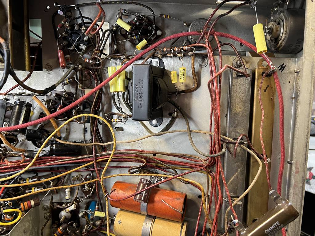
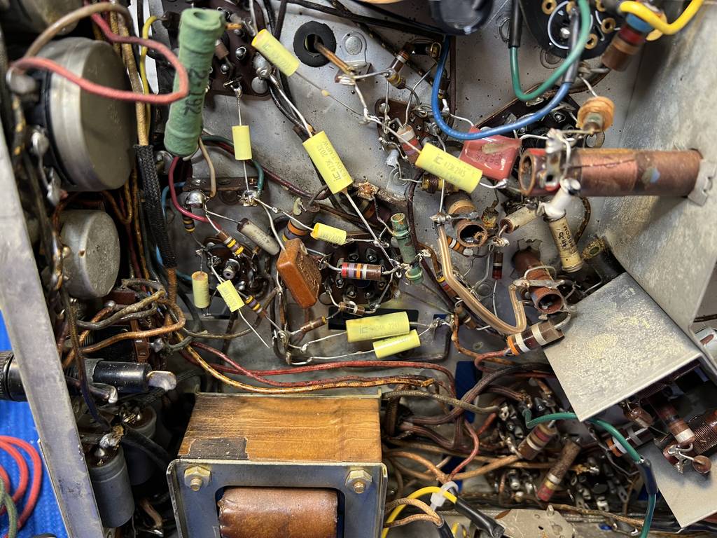
More of the chassis

Area under the HV cage

OK...so, when the relay kicks in, I have a dead short...somewhere. I'm certainly not asking anyone to review these photos and tell me where it is. I'd just like some guidance on where to start methodically running it down. My first thought was to go through my replacements one by one checking for accuracy but IDK if that's the best way. If desired, I can post photos and details of any area on the chassis and describe what's going on. Any and all advice is greatly appreciated!!!!
Sorry if my ranting about criticisms offended anyone. I'm embarrassed by some of the dumb things I do! The Top Dogs here have always been kind, encouraging, helpful and reassuring.
This post is not as comprehensive as I would have liked it to be but I wanted to get something out there to get started.
Cheers!