Quote:
Originally Posted by Phil Nelson

There isn't much else to tweak in that circuit
|
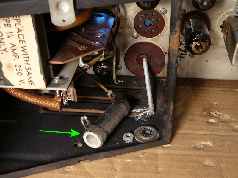
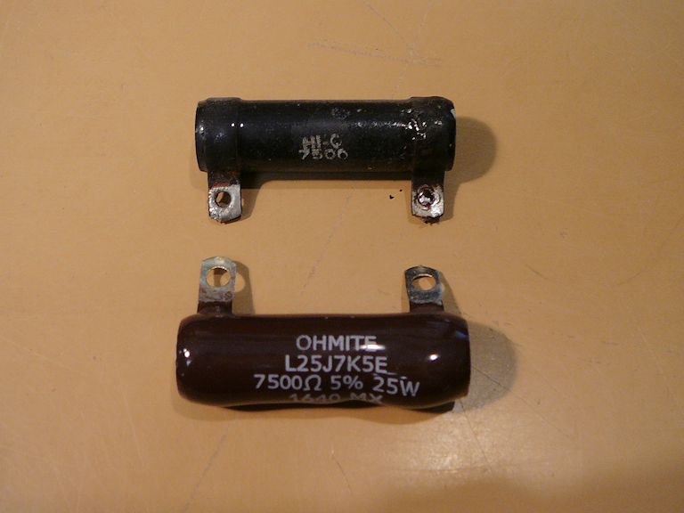
In the damper circuit, there is a 25-watt wirewound filter resistor (R86), which turned out to be open!

It's one of those guys that stands upright inside the high voltage cage.
Replacing it cured the worst horizontal geometry problems, but then the width was insufficient. Earlier in the project, I had removed a .25 paper cap that someone tacked in parallel with the width coil (L8).

I experimented with a decade box and found that .25 was indeed about the right value to bring the width back into range.
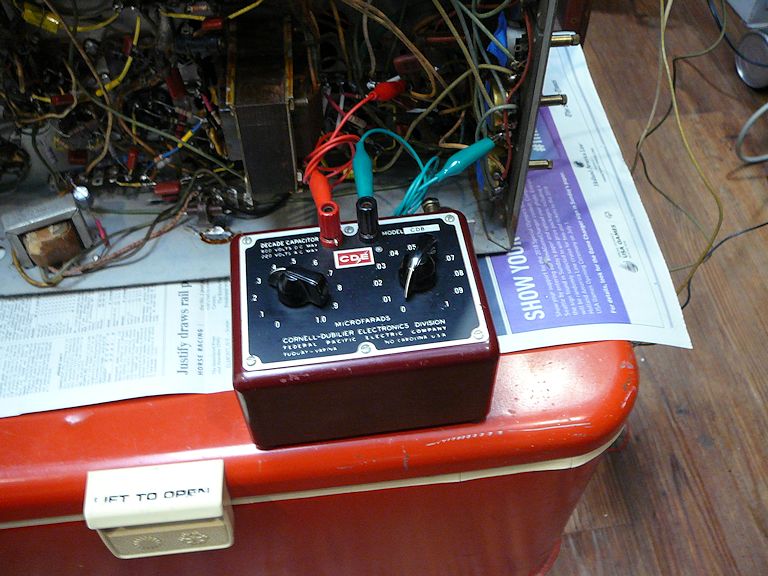
I guess the guy who added that cap was onto something

There's more tweaking to do -- there is still a very slight crushing of width on
both far edges -- but I have a watchable picture for the first time in this project.
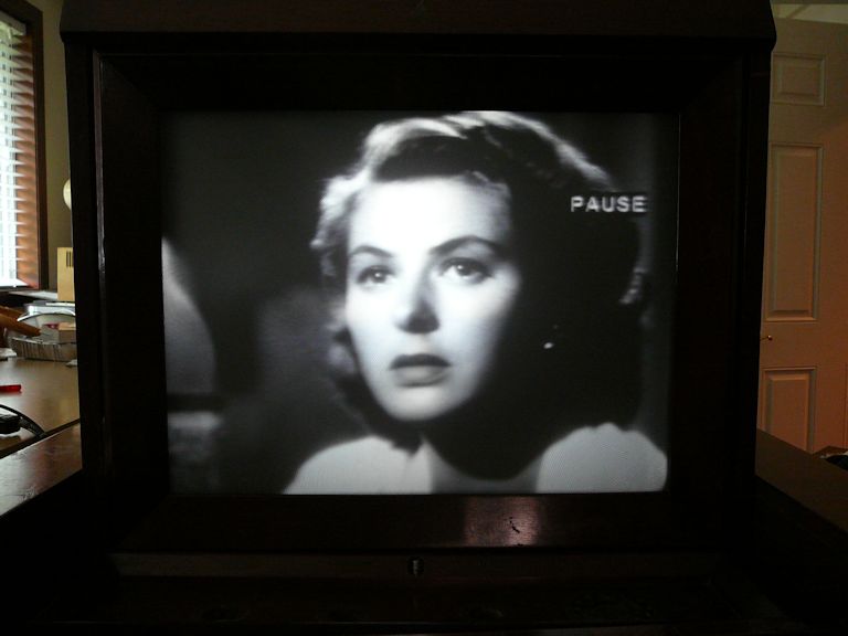
Yay!
Phil Nelson
Phil's Old Radios
https://antiqueradio.org/index.html