Thank you very much so far.
I think I've gone as far as I can without asking for help, but I don't know how to proceed.
I've opened up the cable and connector and I'm ready to solder. I've found that the pinout is as follows:
1-Red-Inner Red Coaxial Wire
2-Green-Inner Green Coaxial Wire
3-Blue-Inner Blue Coaxial Wire
4-ID2-Unknown
5-Ground HSync-Outer Black Coaxial Wire
6-Red Return-Outer Red Coaxial Wire
7-Green Return-Outer Green Coaxial Wire
8-Blue Return-Outer Blue Coaxial Wire
9-Pin Missing
10-Ground Vsync-Little Black Wire
11-ID0-Unknown
12-ID1-Red Wire inside Black Coaxial Wire
13-Hsync-White Wire
14-Vsync-Brown Wire
15-ID3-Yellow Wire inside Black Coaxial Wire
The connector has 13 wires, yet 14 pins. The green wire is unaccounted for. How can this be?
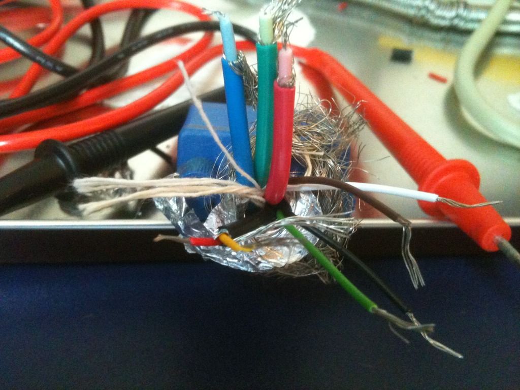
Not to mention red is apparently fine.