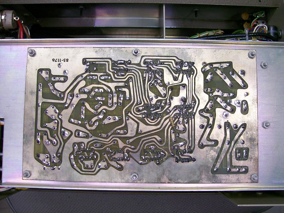
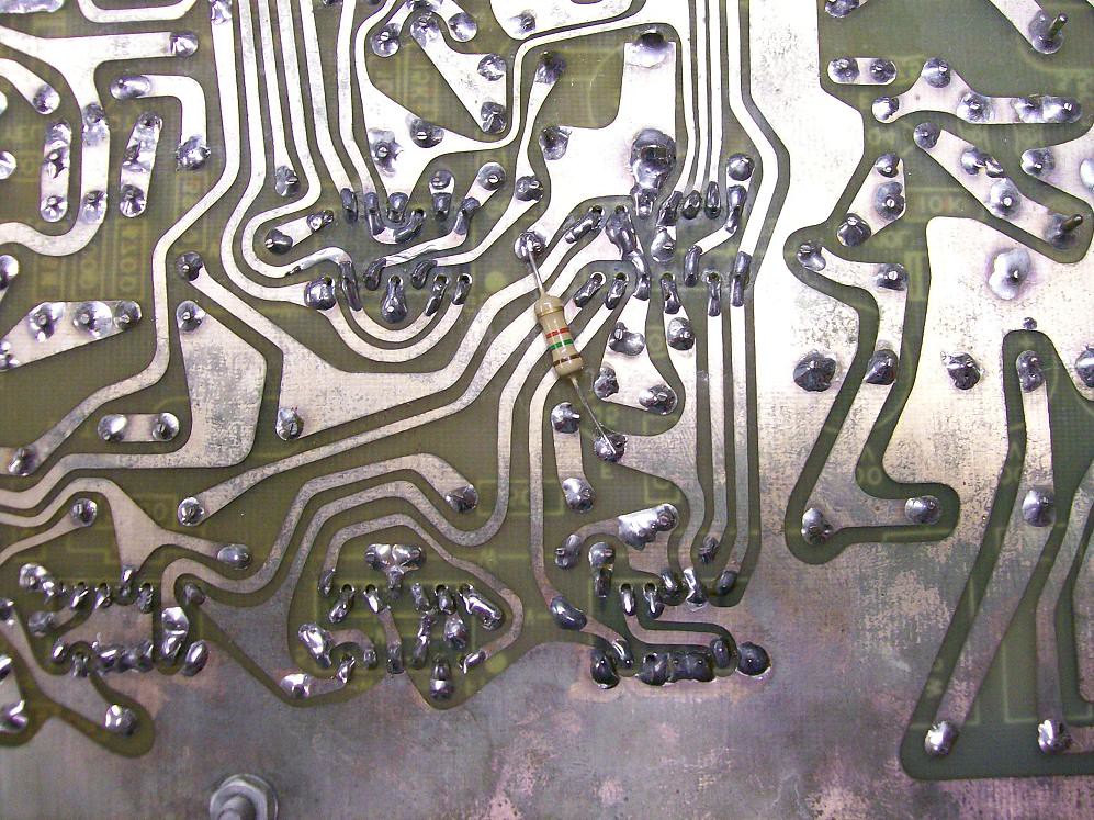
Here's a couple pictures of where I located the 1.5K on the back side of the circuit board. It's between pin 4(ground) and pin 10(input to G1 gate which is IC 9 in the manual). You will need to adjust the Vertical Blanking Width pot(R35) in order to get the best line pattern at the top of the picture. Basically you will be adjusting the width of the vertical blanking pulse, which determines where at the top of the screen the horizontal scan begins. When that pulse is too wide you see the vertical blanking pulse turn off transistion, which is what causes the wiggle in the vertical lines. Hope that makes sense. Let us know how it works out.