Quote:
Originally Posted by robert1

I believe that there is a bad electrolytic capacitor for the video output cathode bias that is bad. i've seen this before. if the doorknob capacitor is failing, there would be HV issues, but from what i see of the pics, this is more like a problem with the video output stages. i would venture to say that a total recap of the set will fix the problem.
|
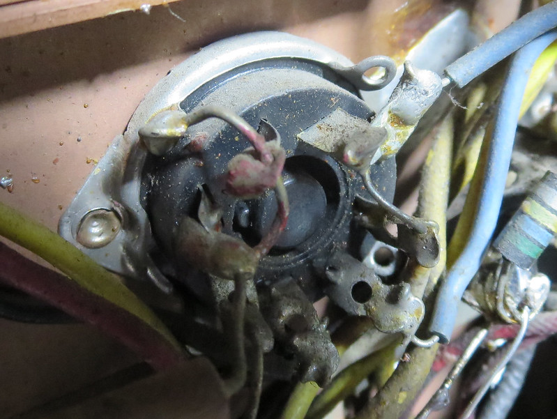
You were close. There is no cathode bias cap on the 6AC7 video output tube, but the problem was a filter cap. While investigating, I was surprised to see that the filament ground wire on pin 2 wasn't soldered. It also appears to have Glyptal (red insulating varnish) paint on it Weird. It must be making good enough contact because the tube is warm. I cleaned off the gunk and soldered it securely.

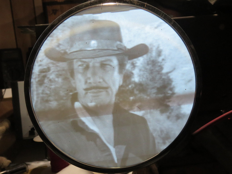
I then went hunting with a scope and found a huge 200V triangle waveform at around 15.75 kH on the B+ boost rail. The old 20uF cap still wired in must be dead. I temporarily tacked in a new 22uF and viola - problem solved.


I have a few more old caps to replace then I'll check the alignment before installing a new 16GP4.
Normally, I would do a shotgun recap but I find it can be fun and instructive to do it in stages too.
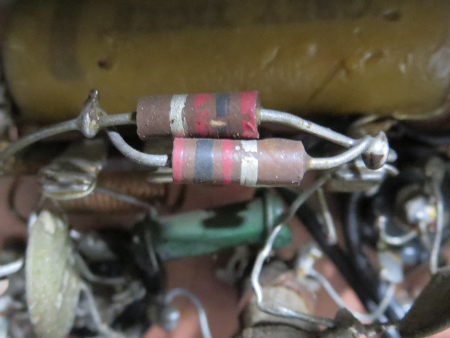
One other thing I've noticed in this and other 1950 era TVs is a weird assortment of resistors. Also some in series or parallel to get the needed value.
They must have really been hurting for 1K resistors. A bunch are actually 1.2K and here are two 2K in parallel. They even used a dogbone.

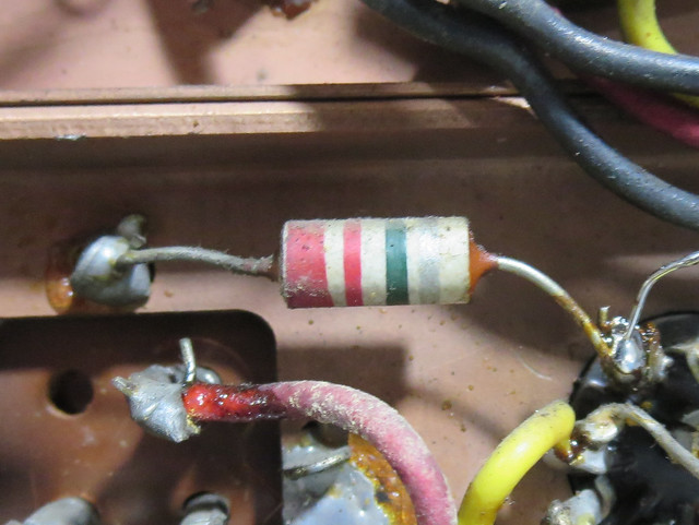
I thought this was a ceramic cap at first, but no, it's a 2.2 M resistor.

I figure the big demand for consumer electronics and the Korean war was causing shortages.