
|
|
|
|
|
#1
 08-20-2016, 10:20 AM
|
|||
|
|||
|
Quote:

|
|
#2
08-20-2016, 11:32 AM
|
|||
|
|||
|
Quote:
Good luck, please make sure to document and post pictures.
|
|
#3
08-20-2016, 11:36 AM
|
|||
|
|||
|
Just to let everyone know, this set uses a 14CP4 CRT. It is a model 14R12 with a 20T1 chassis. Brown Bakelite cabinet.
|
|
#4
08-20-2016, 10:19 AM
|
|||
|
|||
|
Quote:
Thanks for the relocation. I was going to shut down the For Sale thread and start a restoration thread.
|
|
#5
09-19-2016, 09:11 AM
|
||||
|
||||
|
Why did you pull the 1B3 ? No harm is gong to come from leaving it installed.
|
| Audiokarma |
|
#6
09-19-2016, 10:37 AM
|
|||
|
|||
|
Quote:
|
|
#7
09-19-2016, 11:51 AM
|
||||
|
||||
|
Quote:
__________________
Tom C. Zenith: The quality stays in EVEN after the name falls off! What I want. --> http://www.videokarma.org/showpost.p...62&postcount=4
|
|
#8
09-19-2016, 11:57 AM
|
|||
|
|||
|
Quote:
On the horiz out, remove the entire tube, not just the plate cap. Just lifting the plate cap, can still destroy the H.O, because of no plate voltage.
|
|
#9
09-19-2016, 12:37 PM
|
|||
|
|||
|
All good stuff. Thanks guys for the tips. I'm going to check for the high voltage from the transformer at the 5U4G tube. I didn't do that yet.
|
|
#10
09-19-2016, 11:17 AM
|
||||
|
||||
|
Sure, I understand. What I typically do is pull the 5U4 rectifier tube for the first power up. That will kill B+ to the entire set and only the filaments get power. Then I put my DMM in AC mode and probe the 5U4 socket. Should have around 5 VAC for the filament and 700-800 between the plates. That's a quick way to see if the power transformer is any good without risking damaging anything.
|
| Audiokarma |
|
#11
09-21-2016, 01:08 PM
|
||||
|
||||
|
Here are my best guesses
1st 47 pF (might be 4700 ?) 2nd 470 pF 3rd 82 pF 4th 47 pF 5th 1000 pF
|
|
#12
09-21-2016, 09:00 PM
|
|||
|
|||
|
Quote:
#1 is listed as C403 .0047mfd mica or 4700pf #2 is listed as C404 .006mfd mica or 6000pf #3 is listed as C413 82mmfd mica or 82pf #4 is listed as C420 470mmfd 5% mica or 470pf #5 is listed as C421 .001mfd 5% mica or 1000pf Both Sams and Rider's agree on the values. As you can see #1 and #2 differ. #3-5 agree with both parts lists. BTW the part designators are from Rider's. I then remembered that my multimeter can check the values of capacitors. Both #1 and #2 measured out to 4.70nf or 4700pf. I really don't know why the color code is so difficult to determine the value of these caps. Looks like I'll be using 4700pf 5% 500V Silver Micas for their replacement. I'm including the schematic from Rider's.
|
|
#13
09-21-2016, 01:20 PM
|
||||
|
||||
|
Remember most schematics don't reflect some or all production changes (Admiral had MANY), schematics (especially Sam's) had errors/typos, and that if it was factory wired the way it currently is then it is likely to work better being left alone than it will if you make it match the schematic. So it is most advisable to leave the factory wiring config alone till you finish recap and other avenues of troubleshooting.
Also you probably know this, but micas rarely fail and often are in circuits that require re-alignments after cap change (sometimes even lead dress changes can upset it). Leave micas under 1000pF alone unless you have good reason to believe they are bad. Ones over 1000pF often are not really micas, but paper caps in mica's clothing, and as a matter of policy I normally change them.
__________________
Tom C. Zenith: The quality stays in EVEN after the name falls off! What I want. --> http://www.videokarma.org/showpost.p...62&postcount=4
|
|
#14
09-21-2016, 09:24 PM
|
||||
|
||||
|
OK. I can see the 2nd one has a red multiplier dot I thought was brown earlier. As for the first. I think it's a variant that has three digits (yellow. violet, black) then a X10 multiplier (brown).
As Tom mentioned, Admiral did many production run changes. You should have a run # stamped somewhere on your chassis.
|
|
#15
09-21-2016, 10:13 PM
|
||||
|
||||
|
I dug up a whole page of 20T1 production changes in the Wallace Teleaide for Admiral. Click for a larger version.
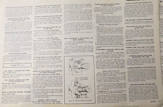 No mention of C404 but this may explain it. There were parts shortages due to the Korean conflict and high consumer demand so substitutions were made. 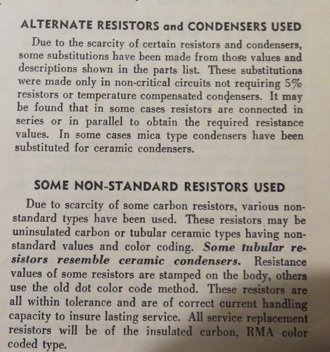
|
| Audiokarma |
 |
| Thread Tools | |
| Display Modes | |
|
|


 Hybrid Mode
