
 |
|
#46
|
|||
|
|||
|
The parts are ordered.
I ordered my E-Caps from Digikey and they will be here in a day or so. So I thought that I would start on re-stuffing the 2 E-Caps. 1 E-Cap is a 4 section and the other is 3 sections. Basically what I do is to remove both cans from the chassis, cut them at the base, clean out the cans, and build up the E-Caps using a new base from a donor E-Cap. This way the terminals are nice and new, but more important, the twist lock tabs are new and shouldn't break off when installing the re-stuffed E-Cap. 1) The first thing I did was dig out my donor cap for the new base. I got a bunch of these at an auction for almost nothing. The E-Caps are all 4 sections. This way I can use their bases on anything I should need on my TV's and radios. 2&3) I cut the bases off using my band saw. I cut just above where the smaller diameter can meets the base. Once the base is cut off, I true up the base using a flat piece of 80 grit sandpaper to bring the edge of the can down to nothing so only the base is left. I then drill a 5/32 hole in the center for the wires to pass through. I suppose you could drill a hole by each terminal and then 1 for the ground wire. 4) I then take some 1" schedule 40 PVC sprinkler pipe and true up 1 end using my disc sander and 90 degree guide. Once trued up I mark that end with an arrow using a Sharpie. I then mark off a 1 inch mark and again cut off the 1 inch piece using my band saw. I then true up the end of the remaining stock using my disc sander and 90 degree guide. Then I mark off 1 inch and cut another piece of PVC pipe. I then clean up the edges using my hobby knife and some 220 grit sandpaper. 5) Then I mix up some 15 minute epoxy and apply it to the end marked by the arrow using a flat toothpick. I then place it on the base and then again using a flat toothpick, I apply a small amount of epoxy around the inside perimeter. Once that is done, I make sure there is no epoxy on the outside of the PVC tube. This would cause a problem when the can from the original E-Cap is placed over the PVC pipe and pushed down. 6) I let them assembly to dry overnight. I'll then add the new E-Caps to the new base assemblies. Then using the original E-Caps I'll cut off the cans from their bases and true up the cans to be placed over the new re-stuffed bases. 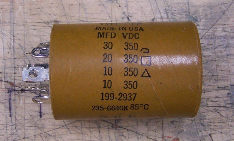 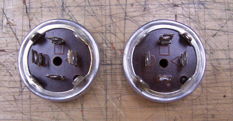 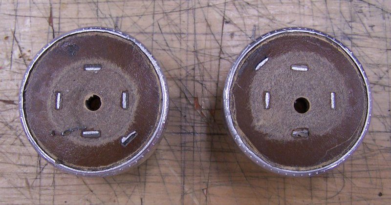 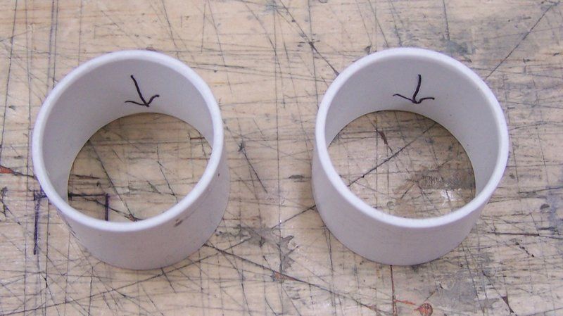 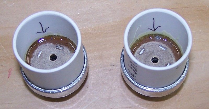
Last edited by Crist Rigott; 12-03-2016 at 03:36 PM. |
|
#47
|
|||
|
|||
|
My E-Caps came in today so I decided to build them up.
I use hot glue to hold them together and some 600 volt solid wire for the leads. I color code each cap and make notes as to what cap, wire color, goes to each symbol. I want to match the originals. On the C2 which has only 3 caps, I used some balsa to from some spacers for the lower cap. This help stabilized the whole thing. The pics speak for themselves. Later tonight, I cut off the original cans, clean them and then the E-Cap re-stuffing will be finished and they'll be ready to install into the chassis. 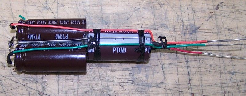 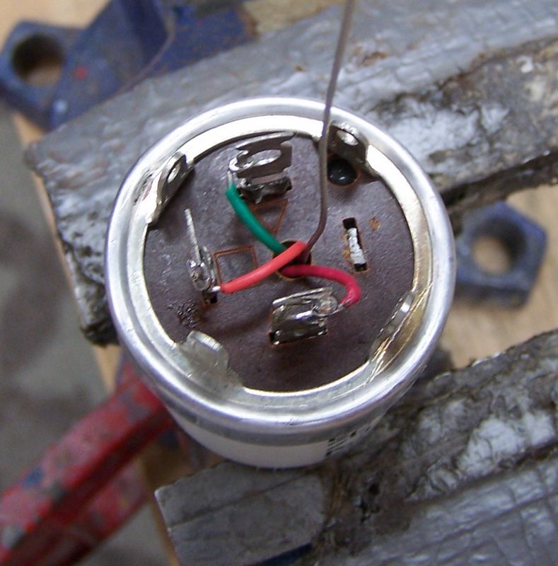 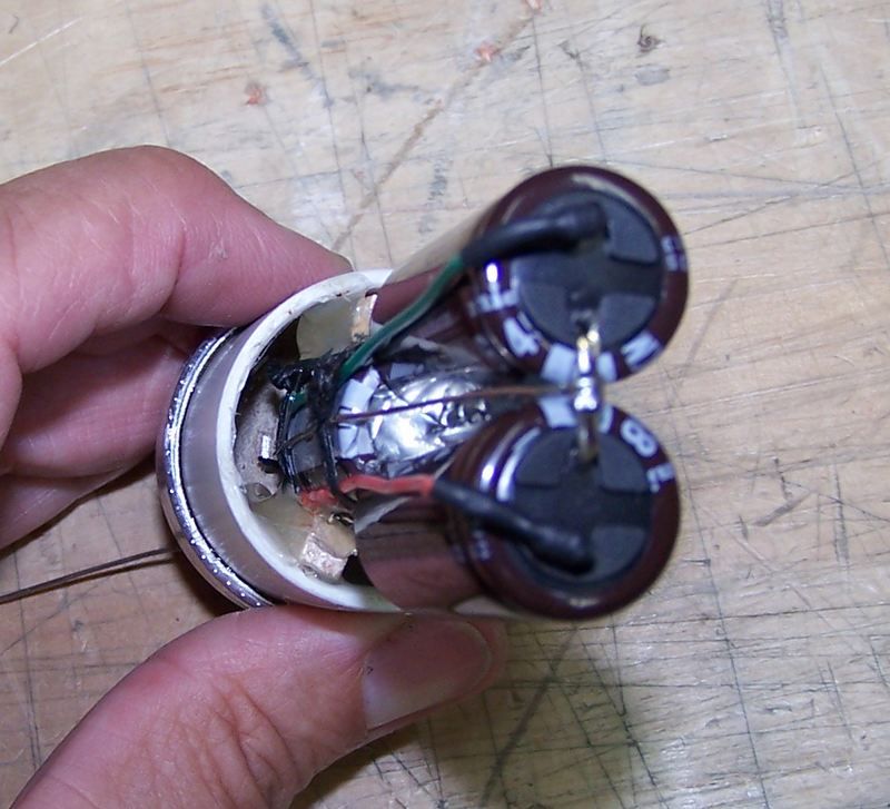 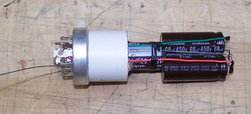
Last edited by Crist Rigott; 12-03-2016 at 03:25 PM. |
|
#48
|
|||
|
|||
|
Nice very nice :-) All the best,Tom.J
|
|
#49
|
|||
|
|||
|
Last edited by Crist Rigott; 12-03-2016 at 03:21 PM. |
|
#50
|
||||
|
||||
|
That's a very neat E-cap rebuilding method you have.
 I need to get me some of that schedule 40 PVC tubing. One obvious short cut would be to saw the tops off the cans while the bases are still mounted and wired to the chassis. Unfortunately some times they land in locations too tight to get a jewelers saw and sanding block in there. I need to get me some of that schedule 40 PVC tubing. One obvious short cut would be to saw the tops off the cans while the bases are still mounted and wired to the chassis. Unfortunately some times they land in locations too tight to get a jewelers saw and sanding block in there.
|
| Audiokarma |
|
#51
|
|||
|
|||
|
Thanks Kevin.
I wired in the E-Cap cans and tacked in the 2 other E-Caps. I then carefully powered up the chassis. At 110V mains, I got 208V B+ ( 238 listed in Sams), and a raster. No audio though. Though the "hash" went up and down with the volume control. Looks like all the front panel controls did something. After about 2 minutes, I heard a "pop" from under the chassis. I quickly powered down and did a visual. Didn't see anything. So I powered it back up and still no audio and this time no raster. No HV either. So I shut it down till I can replace all the paper caps and such. When looking this thing over when I first got it, I was amazed that there weren't any shorts because of the way the components were wired in. When replacing the caps and resistors, I do a complete and through job on lead dress. I'm expecting my order from Just Radios to get here early next week. |
|
#52
|
||||
|
||||
|
Just don't change IF lead dress...You may need to do an alignment afterwards if you do.
__________________
Tom C. Zenith: The quality stays in EVEN after the name falls off! What I want. --> http://www.videokarma.org/showpost.p...62&postcount=4 |
|
#53
|
|||
|
|||
|
Yeah, the IF section is nicely done. It's the other part that needs a lot of TLC.
|
|
#54
|
|||
|
|||
|
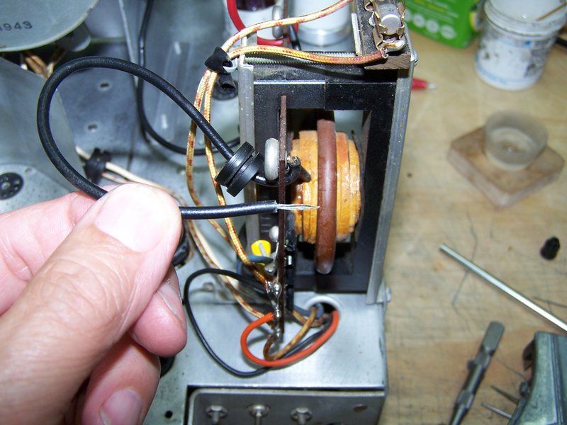
Guys, I need to replace the wire from the cap of the 6BQ6GT to the flyback. The cap connector came off and when I stripped the wire back some, it was all green and the green just powdered off. Not good. I need to replace this wire that is about 6 inches long. Looks to be about 20 awg. I'm thinking the some UL1015 600 volt stranded wire would work.
Last edited by Crist Rigott; 12-03-2016 at 03:21 PM. |
|
#55
|
|||
|
|||
|
The insulation on the wire you are thinking of using will not last very long due to the 3kv to 4.5kv pulse on that lead. I do not have the Belden type number in front of me but I would use a bit of focus lead from a BPC junker for that lead. All the best, Tom.J
|
| Audiokarma |
|
#56
|
|||
|
|||
|
Quote:

|
|
#57
|
|||
|
|||
|
I have a junker 19" B&W tv I got off the curb one day. I'll get the wire off of the HV anode wire from this tv.
I didn't know what kind of voltages to expect. Now I do. |
|
#58
|
||||
|
||||
|
If you have an old CRT monitor kicking around, you could steal its high voltage wire off it. Those monitors also usually have a fair amount of high voltage caps of the sort useful in TV restorations.
__________________

|
|
#59
|
|||
|
|||
|
Good idea, but no old monitors laying around. I'll get the HV wire from the 19" TV.
|
|
#60
|
|||
|
|||
|
Well, I just stripped the wire back another 3/8 inch and it was good clean wire. I cleaned up the plate cap connector and re-soldered it back on to the wire. All is well now. I do have some 20K wire I salvaged from the 19" TV.
I've started on changing a few resistors that were basically stand alone. I'm waiting for my Just Radios order to come in. Then the recapping will take place in earnest. |
| Audiokarma |
 |
|
|