
|
|
|
#31
 08-04-2012, 01:50 PM
|
|||
|
|||
|
Quote:

|
|
#32
08-04-2012, 02:20 PM
|
||||
|
||||
|
I replace selenium rectifiers with type 1N4007 diodes, which are more than adequate and work fine. They cost a few cents. Take the old rectifier completely out of the circuit (don't bridge the diode across it).
Phil Nelson Phil's Old Radios http://antiqueradio.org/index.html
|
|
#33
08-04-2012, 04:18 PM
|
||||
|
||||
|
Yep, It's that easy. I leave it in there for looks but totally out of circuit.
__________________
My TV page and YouTube channel Kyocera R-661, Yamaha RX-V2200 National Panasonic SA-5800 Sansui 1000a, 1000, SAX-200, 5050, 9090DB, 881, SR-636, SC-3000, AT-20 Pioneer SX-939, ER-420, SM-B201 Motorola SK77W-2Z tube console McIntosh MC2205, C26 
|
|
#34
08-04-2012, 04:41 PM
|
|||
|
|||
|
Quote:
Last edited by snelson903; 08-04-2012 at 04:51 PM.
|
|
#35
08-04-2012, 05:30 PM
|
||||
|
||||
|
Quote:
I also like to replace the series filament dropping resistor with a diode or capacitor when possible.
|
| Audiokarma |
|
#36
08-04-2012, 09:36 PM
|
|||
|
|||
|
Quote:
Last edited by snelson903; 08-04-2012 at 11:26 PM.
|
|
#37
08-08-2012, 07:57 PM
|
||||
|
||||
|
Wow, that's huge!
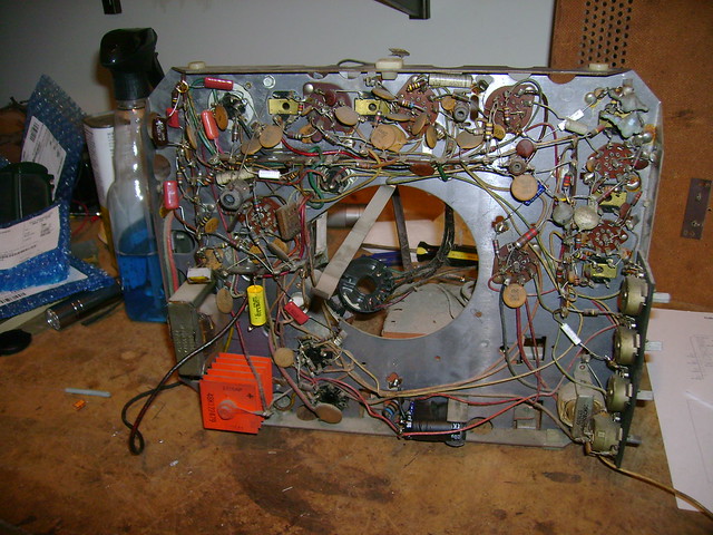
I've been experimenting with replacing the selenium rectifier. Through trial and error I determined that using a 1N4007 silicon diode plus a 12 ohm, 5W resistor produces the desired +125VDC with a 120 VAC AC line voltage. That got me thinking that if I could bump the existing fusistor up from 3 to 15 ohms, it would make a cleaner modification. Well, I didn't have any on hand, but I do have some modern 4.7 ohm fusible resistors so I combined that with a regular power resistor. While I was at it, I figured why why not add the diode too ? It works fine, but the diode is getting pretty hot so I think it might be best to relocate it away from the resistors. 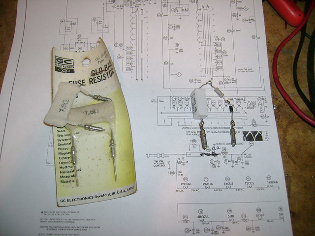
Last edited by bandersen; 08-08-2012 at 08:06 PM.
|
|
#38
08-08-2012, 11:22 PM
|
|||
|
|||
|
how many watt is the small resister ,in the picture it looks like a 1/2 watt one, if it is i wonder if that is contributing to the diode heating up . how much is the current draw is on that circuit ,i think the 330v supply on my zenith iv been rebuilding is about 450ma you might just need to up the small resister to 1 watt and see if the diode stays cooler . does the diode heat up fast or does it take alittle time. its looks like a neat idea does it plug into a base socket that easy to get at, if it does you could put everthing on a small breadboard and have the two prongs sticking out the end and it could be a fusible filter setup that can kwick change out.
|
|
#39
08-09-2012, 01:07 AM
|
||||
|
||||
|
The smaller one is a 2W fusible resistor. It's made out of ceramic and is designed to take the heat. After a while though, I discovered that the solder was melting!
Probably should use a high temp solder like silver solder. It's drawing about 400ma so I figure that little 4.7 ohm resistor is putting out less than 1 W. I decided to just use one of those old 7.5 ohm globar fuse resistors and locate the diode near where the older selenium rectifier had been. Last edited by bandersen; 08-09-2012 at 01:14 AM.
|
|
#40
08-09-2012, 03:18 AM
|
|||
|
|||
|
is normal for that to run that hot that it would start to melt the solder ,i think it would burn out before that you know ,i like how they named that resister [ glo-bar ] i have seen them after they have been hot and darken the outside in older stuff , i hope they dont glo before they blow l o l
Last edited by snelson903; 08-09-2012 at 03:27 AM.
|
| Audiokarma |
|
#41
08-10-2012, 10:36 PM
|
||||
|
||||
|
I'm curious what others have used to replace fusistors with. Power resistor + fuse ?
|
|
#42
08-12-2012, 03:08 PM
|
||||
|
||||
|
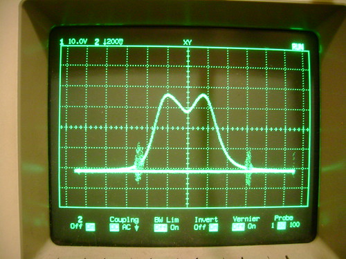
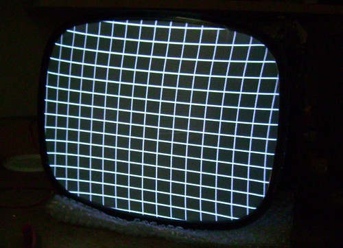
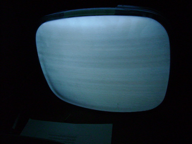
I performed an alignment and tweaked the linearity. The response curve was lopsided when I started and it took a while to get symmetrical with a bandwidth of about 3.5 MHz. There's a bit of pincushion, but otherwise it's not bad.
Last edited by bandersen; 08-12-2012 at 03:14 PM.
|
|
#43
08-12-2012, 03:48 PM
|
|||
|
|||
|
i dont think you can make that anymore perfect than it is,they probley wasn't that good new ,nice sharp picture, good work .
|
|
#44
08-12-2012, 04:49 PM
|
||||
|
||||
|
Thanks!
I just found a great photo of this set in excellent condition: http://farm8.staticflickr.com/7014/6...aca97d8d_b.jpg Time to go knob hunting Last edited by bandersen; 08-12-2012 at 10:35 PM.
|
|
#45
08-12-2012, 07:12 PM
|
||||
|
||||
|
WOW!! Really a nice work!!!
|
| Audiokarma |
 |
|
|


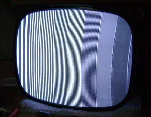
 Now to try feeding in some signals.


 Linear Mode

