Videokarma.org

Go Back   Videokarma.org TV - Video - Vintage Television & Radio Forums > Early B&W and Projection TV

We appreciate your help

in keeping this site going.
Reply
 
Thread Tools Display Modes
  #1  
Old 06-28-2017, 05:18 PM
Notimetolooz's Avatar
Notimetolooz Notimetolooz is offline
VideoKarma Member
 
Join Date: Mar 2014
Location: Dallas, TX
Posts: 548
Quote:
Originally Posted by jr_tech View Post

200 volt rating for the 82 uuf cap should be fine, as the 150 k resistor and the 2 33 k resistors in series form a voltage divider network. The total resistance of the divider is 216 k (150+33+33).... 66k out of 216 k is about 30% .... 30% of 265 volts is about 80 volts. When the tube warms up and starts drawing current, the voltage at that point drops about 10 volts more to 70 volts.

jr
Jr is right about the voltage across the 82 pf increasing every time the set starts up from cold because the tube isn't drawing current. This does point out however that when something is designed that it is difficult to cover all the bases. If the 33K resistors in K4 increase a lot in value or open up then the voltage will be higher. This could also happen if in troubleshooting someone disconnects K4. Its hard to foresee every possibility.
Reply With Quote
  #2  
Old 06-28-2017, 05:37 PM
Crist Rigott Crist Rigott is offline
VideoKarma Member
 
Join Date: Oct 2015
Location: Waxahachie, TX
Posts: 1,506
Quote:
Originally Posted by Notimetolooz View Post
Jr is right about the voltage across the 82 pf increasing every time the set starts up from cold because the tube isn't drawing current. This does point out however that when something is designed that it is difficult to cover all the bases. If the 33K resistors in K4 increase a lot in value or open up then the voltage will be higher. This could also happen if in troubleshooting someone disconnects K4. Its hard to foresee every possibility.
I have a 200v cap coming. On the other hand, I can always order a 82pf 1KV SMD that will fit the through hole pads well enough. Maybe I should hust go with one of those?
Reply With Quote
  #3  
Old 06-30-2017, 09:28 PM
Crist Rigott Crist Rigott is offline
VideoKarma Member
 
Join Date: Oct 2015
Location: Waxahachie, TX
Posts: 1,506
I'm done with the design of the Couplets. If you get a chance would you mind going over them to see if I have them correct?

Thanks.

Last edited by Crist Rigott; 09-23-2018 at 09:12 AM.
Reply With Quote
  #4  
Old 06-27-2017, 03:04 PM
bandersen's Avatar
bandersen bandersen is offline
RCA 741PCS
 
Join Date: Mar 2009
Location: Chicago, IL
Posts: 8,106
Hmm, 0.7A seems high, but I can't fault your math. I'd still use either a resistor or a thermistor. It'll give the set a soft start and help preserve those old parts.
__________________
Here are my Vintage Radio & TV YouTube Channel and Photo Gallery
Reply With Quote
  #5  
Old 06-28-2017, 11:33 AM
DavGoodlin's Avatar
DavGoodlin DavGoodlin is offline
Motorola Minion
 
Join Date: Aug 2011
Location: near Strasburg PA
Posts: 3,413
Quote:
Originally Posted by bandersen View Post
Hmm, 0.7A seems high, but I can't fault your math. I'd still use either a resistor or a thermistor. It'll give the set a soft start and help preserve those old parts.
Motorola (CDTS-581) and RCA (CTC11) used inrush current limiters in some early-1960's TVs to lessen inrush on tube heaters in particular - I use the CL-90 made by GE. It is 120 ohms cold and rated for 2 amps. Works for most all monochrome TVs and tube radios. I like to think a transformer can be made to live longer.

The CL-90 works for almost everything but color TV, then a CL-70 has lower cold resistance (47 ohm) but rated at 4 amps, which most older sets draw up to.
__________________
"When resistors increase in value, they're worthless"
-Dave G
Reply With Quote
Audiokarma
  #6  
Old 07-01-2017, 08:23 AM
nasadowsk's Avatar
nasadowsk nasadowsk is offline
Damn does run fast…
 
Join Date: Jul 2004
Location: Catawissa, PA
Posts: 948
I think SMDs would lead to a smaller package, and then you could epoxy dip it for an authentic look. And better reliability.

My only question is, can they take any voltage spikes on them? This might be an issue. (Don't forget startup, before the tubes are conducting...)

What are you using for the PCB design, btw?

If there was enough demand, you could get them made by a PCB place and stuffed and all. With the plethora of places overseas, this is surprisingly cheap now...
Reply With Quote
  #7  
Old 07-01-2017, 02:05 PM
Notimetolooz's Avatar
Notimetolooz Notimetolooz is offline
VideoKarma Member
 
Join Date: Mar 2014
Location: Dallas, TX
Posts: 548
On K7 the junction of the 560 pf and 3300 pf needs to connect to pin 2.
I wish the schematics were drawn easier to follow, more nearly like your layout.
Reply With Quote
  #8  
Old 07-01-2017, 05:31 PM
jr_tech's Avatar
jr_tech jr_tech is online now
VideoKarma Member
 
Join Date: Sep 2009
Posts: 4,522
Quote:
Originally Posted by Notimetolooz View Post
On K7 the junction of the 560 pf and 3300 pf needs to connect to pin 2.
I wish the schematics were drawn easier to follow, more nearly like your layout.
Good catch! I missed that one on my first look. Like the way the distributec R/c was done in k4.

jr
Reply With Quote
  #9  
Old 07-01-2017, 07:14 PM
Crist Rigott Crist Rigott is offline
VideoKarma Member
 
Join Date: Oct 2015
Location: Waxahachie, TX
Posts: 1,506
Quote:
Originally Posted by Notimetolooz View Post
On K7 the junction of the 560 pf and 3300 pf needs to connect to pin 2.
I wish the schematics were drawn easier to follow, more nearly like your layout.
Wow, I missed that there was a connection there! Thanks.
Reply With Quote
  #10  
Old 07-02-2017, 09:52 PM
Crist Rigott Crist Rigott is offline
VideoKarma Member
 
Join Date: Oct 2015
Location: Waxahachie, TX
Posts: 1,506
I made the PCB's today. Basically I use the Press-N-Peel method. Or another name is Toner Transfer. I run the sheet through my laser printer set on 1200dpi and the iron on the pattern on a clean, really clean copper side of the board. Peel off the sheet, then etch, drill, and trim to size.

Here are the boards with the toner transferred to the copper.

Last edited by Crist Rigott; 09-23-2018 at 09:13 AM.
Reply With Quote
Audiokarma
  #11  
Old 07-03-2017, 01:30 AM
Crist Rigott Crist Rigott is offline
VideoKarma Member
 
Join Date: Oct 2015
Location: Waxahachie, TX
Posts: 1,506
Here they are. Ready to encapsulate. Can you find the 82pf 200V cap?

Last edited by Crist Rigott; 09-23-2018 at 09:13 AM.
Reply With Quote
  #12  
Old 07-03-2017, 07:44 PM
irext's Avatar
irext irext is offline
VideoKarma Member
 
Join Date: Dec 2016
Posts: 69
Very neat. Would you bother to encapsulate them? They look very nice as is. Other than authenticity I can't see a reason to. In the (admittedly highly unlikely) event of a component failure you can replace a component if left unencapsulated.
Reply With Quote
  #13  
Old 07-04-2017, 11:24 AM
jr_tech's Avatar
jr_tech jr_tech is online now
VideoKarma Member
 
Join Date: Sep 2009
Posts: 4,522
Very nice!
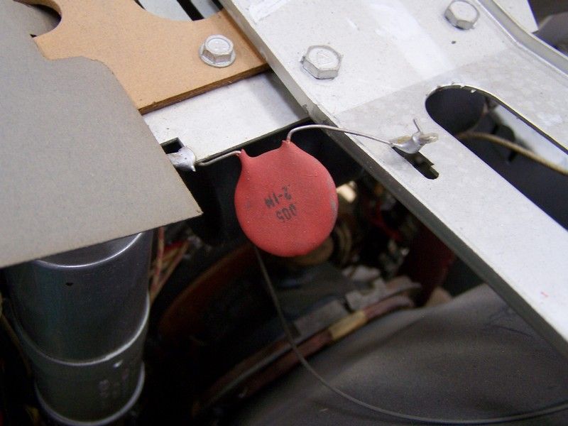
Out of curiosity, where is K8 located in the set? I don't remember seeing it when I did mine a few weeks ago.

jr
Reply With Quote
  #14  
Old 07-04-2017, 12:53 PM
Crist Rigott Crist Rigott is offline
VideoKarma Member
 
Join Date: Oct 2015
Location: Waxahachie, TX
Posts: 1,506
Quote:
Originally Posted by jr_tech View Post
Very nice!
Out of curiosity, where is K8 located in the set? I don't remember seeing it when I did mine a few weeks ago.

jr
Thanks. K8 is located on the top of the main chassis. It goes between the main and CRT chassis. Looks a lot like a ceramic disc capacitor.


Last edited by Crist Rigott; 07-04-2017 at 12:58 PM.
Reply With Quote
  #15  
Old 07-04-2017, 01:07 PM
jr_tech's Avatar
jr_tech jr_tech is online now
VideoKarma Member
 
Join Date: Sep 2009
Posts: 4,522
Slaps forehead!
I remember unsoldering a "ceramic cap" when I pulled the chassis... since I generally leave ceramic caps alone, I paid no attention to it.

jr
Reply With Quote
Audiokarma
Reply


Posting Rules
You may not post new threads
You may not post replies
You may not post attachments
You may not edit your posts

BB code is On
Smilies are On
[IMG] code is On
HTML code is Off

Forum Jump


All times are GMT -5. The time now is 02:13 PM.


Powered by vBulletin® Version 3.8.4
Copyright ©2000 - 2024, Jelsoft Enterprises Ltd.
©Copyright 2012 VideoKarma.org, All rights reserved.