
|
|
|
#31
 05-13-2020, 04:39 PM
|
||||
|
||||
|
Okay. I've swapped out the questionable resistor. Not hearing any change.
Any thoughts on what I should check next?
__________________
To keep your tubes running smoothly, make sure to dust underneath the glass as well. 
|
|
#33
05-14-2020, 05:41 PM
|
||||
|
||||
|
I have not. I ordered some spares a while back and they've been delayed. That being said, since this is an AA5 for all intents and purposes, I might could borrow some known good ones from my AM radio and see if that has any impact.
I think I have a signal generator set up somewhere. Would there be any value in checking my audio section with one? I know my speaker output is good since I'm getting some audio hum from it, so it has to be a breakdown somewhere in the signal line, right?
__________________
To keep your tubes running smoothly, make sure to dust underneath the glass as well.
|
|
#35
05-15-2020, 01:45 PM
|
||||
|
||||
|
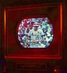
The audio stage is humming, but I'm not getting any signal through. I can get a video of the noise if that will help.
And yeah, I'll pull some tubes from working sets to see if that makes any difference.
__________________
To keep your tubes running smoothly, make sure to dust underneath the glass as well.
|
| Audiokarma |
|
#36
05-15-2020, 02:20 PM
|
||||
|
||||
|
Went ahead and created a video: https://www.youtube.com/watch?v=Nyrr8iUFRzE
I also tried new tubes for everything except the 35Z5. I don't have any spares of that for now, but it also doesn't seem like the problem is in the power supply. I don't believe I have an RF generator, but I do have a digital signal generator I could set up. I haven't used it before but it looks like it might work for running some tests.
__________________
To keep your tubes running smoothly, make sure to dust underneath the glass as well.
|
|
#37
05-15-2020, 05:09 PM
|
||||
|
||||
|
Again, I think the audio section is ok... I hear slight hum which changes with volume control rotation... some volume control scratch ... hum increase with body capacitance... noise from band switching. Do you get noise or change in noise as you connrct a wire to the antenna terminal?
What is the frequency range of the signal generator? can it generate a square wave? (rich in harmonics). jr
|
|
#38
05-16-2020, 08:54 PM
|
||||
|
||||
|
Looks like it can, yeah. I'll have to do a little research into the specific functionality (It's a sort of combo oscilloscope and signal generator) but the interface definitely allows for square waves.
__________________
To keep your tubes running smoothly, make sure to dust underneath the glass as well.
|
|
#39
05-18-2020, 12:25 PM
|
||||
|
||||
|
Quote:
jr
|
|
#40
05-18-2020, 12:40 PM
|
||||
|
||||
|
https://store.digilentinc.com/analog...-limited-time/
One of these things, but I've got an adapter to give it BNC connectors for the Scope functions. It plugs into the computer for the display.
__________________
To keep your tubes running smoothly, make sure to dust underneath the glass as well.
|
| Audiokarma |
|
#42
05-29-2020, 12:11 PM
|
||||
|
||||
|
So I'm thinking my best plan of attack is to use my multimeter to start testing individual resistors and capacitors. It'll take some time, but hopefully that'll give me a better picture of what failed.
I know my main electrolytic is fine (I actually swapped in a spare to be safe) so it's a matter of checking the standard caps and resistors. A quick question, since I haven't gone this in depth before: Do I need to desolder one lead of each cap and resistor before I check it, or can I just turn the power off and start running tests?
__________________
To keep your tubes running smoothly, make sure to dust underneath the glass as well.
|
|
#43
05-29-2020, 03:16 PM
|
||||
|
||||
|
Many parts can be accurately tested without unsoldering a lead... look at the schematic to see if it is connected to anything that could affect the accuracy of the measurement.
It might be a good learning exercise to go ahead and measure all the parts connected in circuit. Then if a part measures out of spec, try to determine why... is the part bad or merely connected to another part that affects the measurement. Verify by disconnecting one end of the part in question. jr
|
|
#44
05-29-2020, 04:50 PM
|
||||
|
||||
|
Good plan. I'll get on that. I'm sure if I work my way down the line the problem will jump out.
__________________
To keep your tubes running smoothly, make sure to dust underneath the glass as well.
|
|
#45
06-02-2020, 09:01 PM
|
||||
|
||||
|
Okay! So I've got a few parts marked as suspect. There's some out of tolerance resistors, some caps that are damaged, and one in particular that has no reading at all across it! So I'm about ready to place an order.
A question, though. There's a component across the tuning capacitor. The original was a small white cylinder, and the SAMS lists that as a capacitor. However, I have a parts chassis I'm pulling a new headphone jack from, and I noticed that that component looks like a resistor there! My set has a few other differences from the SAMS, namely the presence of a small network in place of a few discrete components on the SAMS, and some paper caps going to a few of the antenna jacks that aren't on the SAMS. The parts chassis I have also has that network, but it has a few other differences. I'm including some pictures of both sets, and I'm going to see if I can dig the white cylinder I pulled out of my trash bin. It's somewhere in there, I know. I don't think that's the source of my dead audio, because my audio faded out and the set started smoking before I replaced that part. I did notice a bulge on the side of it when I replaced it, though, and my multimeter is just kind of hanging there (not giving OL, but not displaying any measurement at all) when I try to measure my replacement. Any thoughts here? I can also scan the schematic that came with mine if that would be helpful. I'm not entirely sure how to read that part of it.
__________________
To keep your tubes running smoothly, make sure to dust underneath the glass as well.
|
| Audiokarma |
 |
|
|


 Linear Mode

