
|
|
|
|
|
#1
 07-11-2018, 01:16 PM
|
||||
|
||||
|
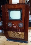
Motorola TS-4J
Can someone confirm what should attach to the selenium rectifiers? Someone replaced mine but there are a lot of loose connections and I'm not sure what goes where. The schematics don't match the spare chassis I have (TS-4J as well).
Thanks, Zach
__________________
"If it isn't broke, you aren't trying hard enough" 
|
|
#2
07-11-2018, 04:35 PM
|
||||
|
||||
|
I've restored several of these and the published schematics are correct. What differences are you seeing in your spare chassis ?
|
|
#3
07-11-2018, 05:21 PM
|
||||
|
||||
|
Quote:
20180711_175753.jpg 20180711_181009.jpg This is the actual wiring of the spare. I realize this isn't in proper schematic form, but I didn't wanna confuse myself.
__________________
"If it isn't broke, you aren't trying hard enough"
|
|
#4
07-11-2018, 05:25 PM
|
||||
|
||||
|
Right the positives do not touch - the rectifier goes in between. Your spare isn't wired right. Maybe someone was trying to fix it ?
|
|
#5
07-11-2018, 06:41 PM
|
||||
|
||||
|
We can only guess. The spare had numerous evident repairs. It blew both the diodes when I installed it in the main chassis, but hopefully all of the caps are still within tolerance.
__________________
"If it isn't broke, you aren't trying hard enough"
|
| Audiokarma |
|
#6
07-12-2018, 06:37 AM
|
||||
|
||||
|
Quote:
|
|
#7
07-12-2018, 11:21 AM
|
||||
|
||||
|
Quote:
__________________
Tom C. Zenith: The quality stays in EVEN after the name falls off! What I want. --> http://www.videokarma.org/showpost.p...62&postcount=4
|
|
#8
07-12-2018, 05:26 PM
|
|||
|
|||
|
Quote:
|
|
#9
07-13-2018, 09:21 PM
|
|||
|
|||
|
If C79 shorted the 200 ohm part of the ballast resistor should of burned up very quickly.
|
|
#10
07-13-2018, 09:33 PM
|
||||
|
||||
|
Quote:
What should the voltage coming off of pin 4 and pin 3 be?
__________________
"If it isn't broke, you aren't trying hard enough"
|
| Audiokarma |
|
#12
07-14-2018, 10:42 AM
|
|||
|
|||
|
Quote:
I just spent a half hour trying to find the B+ source. It seems it's sourced from the cathode of the 12SN7, 2nd clipper. Slightly harder schematic to understand! Even the Sams isn't much better.
|
|
#13
07-14-2018, 11:24 AM
|
||||
|
||||
|
Quote:
__________________
Tom C. Zenith: The quality stays in EVEN after the name falls off! What I want. --> http://www.videokarma.org/showpost.p...62&postcount=4
|
|
#14
07-14-2018, 12:35 PM
|
||||
|
||||
|
Quote:
__________________
"If it isn't broke, you aren't trying hard enough"
|
|
#15
07-14-2018, 10:04 AM
|
|||
|
|||
 Quote:
That set's a little trickier to troubleshoot because it uses a floating B- line instead of a hot chassis.
|
| Audiokarma |
 |
| Thread Tools | |
| Display Modes | |
|
|


 Hybrid Mode
