
|
|
|
#1
 05-07-2016, 09:51 PM
|
||||
|
||||
|
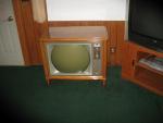
Pilot tv
Ok I'm wondering I'm there is anyone here that knows the pilot tv I ask because I made a mistake paralleling a power supply cap and use the wrong ground or positive being this chassis has both neg and positive on the chassis. And it burned 2 10 ohm resistors 1 going positive and 1 going negative and cooked the 35w4 neg tube . Replaced 2 caps and resistors and the negative tube and now I have a raster but no sound or picture and it's as if there is no antenna hooked to it. If there is any ideas as to what has burned up or could cause this that would help a lot. There is nothing else burned I checked continuity between choke coils in the IF sections and resistors and cannot find anything wrong. Even tried another antenna connection within the house.

|
|
#2
05-09-2016, 04:21 PM
|
||||
|
||||
|
Well ok what I wrote above was off a bit, what happened is I put the set on and the sound and picture was a bit fuzzy and after a few seconds both cleared up so I turned it off and Alittle later put it on and there was no sound or picture then I had done what I had wrote in the last post. Shorting out the neg tube came after because I was in doubt about the caps that were in the set to begin wth so I parallel one and messed up. But the sound and pic just went out and I subbed all Micas in that circuit as well as tubes and found one resistor and replaced it so it seems as if the IF is simply dead and can't find out why. Even tried another source for video and no good. Any help would be greatly appreciated!!! Is there another part of a black and white chassis that would prevent the IF from working ?
Last edited by timmy; 05-09-2016 at 04:58 PM.
|
|
#3
05-10-2016, 12:23 AM
|
||||
|
||||
|
I am thinking that some of what you are saying is confusing to some of the real experts here. I don't consider myself to be one of those guys, but I have been working with old tvs and radios for a number of years, so maybe I can point you in the right direction; I don't know.
First you mention using the "wrong ground" in relation to your power supply and said that your chassis has a positive and a negative. In a wild guess I am thinking that you ran into what I believe is termed a floating ground in the power supply. In short the capacitors negative side doesn't wire to the normal chassis ground. Instead it is wired to an isolated terminal which ties in with other components that are wired the same. The electrolytic caps should be sitting on an insulating base so that the negative side doesn't become grounded to the chassis. I hope I am saying this right. But basically if you thought a cap was bad and went to parallel across it and connected the negative side to the chassis, then you would have problems. By saying that your chassis has a negative and a positive, do you mean that it doesn't have a power transformer and is what we call a "hot chassis?" Perhaps I should just ask if it has a power tranny or not. And by a "neg tube" I see that you are referring to the 35W4 which is a full wave rectifier. It's not a negative tube. Frankly I am surprised that the set employs a 35W4 as I thought that they were found primarily in radios. However, I have only one transformer-less TV set and I think that the 35W4 would be indicative of hot chassis, series strung tube compliment. Most of my sets use 5u4 rectifiers and have a transformer. I'm really not answering any of your questions, but I do think I am sorting some things out. If you are at the point where you are just trying to get video, but you have a good raster (light on the screen) and sound, then you didn't harm the power supply. If you subbed out a bunch of mica caps, I wonder if you did any wax paper. Both are normally very low value microfarad or picofarad and it is possible that you subbed in the wrong caps. Especially with the micas as you had to interpret the color code of dots. It's real easy to get that real wrong and honestly they are the last caps to give trouble. It's the wax paper and black plastic covered caps with colored stripes for value identification that you need to worry about. And finally you need to beware that your positive negative chassis can get you real hurt REAL fast as the chassis is hot. You must get an isolation transformer and you need to get a decent schematic diagram so you can check voltages. But don't check anything until you are isolated or else unplugged where all you can check is resistance. I hope this helps you. I have learned that you will get more interest from the guys who can really help you if you include pictures. People here love pictures! Good luck with your set.
__________________
"Face piles of trials with smiles, for it riles them to believe that you perceive the web they weave, and keep on thinking free"
|
|
#4
05-10-2016, 05:57 AM
|
||||
|
||||
|
Yes it did get confusing about the series of events but I paralleled a cap thinking that a bad cap was the reason why the sound and Picture disappeared but it was not. The Micas that were put in not by me were the wrong values,50pf and 47pf was put in so I subbed the right ones. I used the resistance chart on all tubes in the IF and all others except verticle and horiz and amazingly they were all perfect something you don't always see. This pilot tv don't have the same amount of caps as other b&w tvs but besides everything was changed and it was working fine the only problem I was working on was low hv. As far as a picture there is nothing to show except a blank screen as if the antenna was not hooked to the tv. All I'm trying to find out is why the sound and video just stopped obviously there is something wrong and I'm not getting it but I went over so much that I'm now out of ideas where to go from here.
|
|
#5
05-10-2016, 12:02 PM
|
||||
|
||||
|
Do you have a B&K 1075/76/77 TV analyst? Those units are made for these type of issues. If you have one set it to IF and inject at full blast at the grid of the 3rd IF with the TV's contrast maxed (depending on IF gain you may need to inject at the grid of the second to get a picture or sound). If you don't get picture from the IF, then inject raw video after the detector, and if you then get an image suspect the detector if not the problem is in the video amp or CRT. If you get picture injecting in the IF work your way back through the IF injecting at grids and plates. If all IF stages work then inject IF at the antenna terminals it should pass straight through the tuner....If not the RF amp is having issues or some other open in the signal path has occurred. If IF does pass through the tuner but it will not tune any RF channel then the oscillator in the tuner is likely not working.
IMHO an analyst is essential for these kinds of issues because if you don't have it to isolate the stage the problem is in there are so any stages that could be at fault that at best you will waste your time checking everything in depth to find the problem, or at worst just end up chasing your tail and get nowhere.
__________________
Tom C. Zenith: The quality stays in EVEN after the name falls off! What I want. --> http://www.videokarma.org/showpost.p...62&postcount=4
|
| Audiokarma |
|
#6
05-10-2016, 12:24 PM
|
||||
|
||||
|
Quote:
|
|
#7
05-10-2016, 02:00 PM
|
||||
|
||||
|
Could be you have a bad 6AU6 in the IF based on what you posted in this thread: http://www.videokarma.org/showthread.php?t=266957
The filament voltages should be within about 10% of each other. Either one of those tubes is not really a 6AU6 or it's bad (I'm thinking a heater cathode short) or there's some bad issue with a socket or wiring.
|
|
#8
05-10-2016, 02:59 PM
|
||||
|
||||
|
Quote:
|
|
#9
05-10-2016, 03:59 PM
|
|||
|
|||
|
Do you have good plate voltages to the if tubes?? How about the RF?? A tv I recently completed drove another restorer crazy. I found that There was no B+ to the if plates. Re-establishing B+ voltage corrected the problem.
George
|
|
#10
05-10-2016, 05:28 PM
|
||||
|
||||
|
Ok plate voltages are ok on the 6au6 IF tubes and placing 1 antenna lead on any grids of the 6au6 tubes do nothing. But the 3 12at7 tubes the first 2 there is supposed to be -4.3 and -5.8 volts and I'm getting 1 millivolt . There are 2 coils on the ant and to the RF tube and they check ok.
|
| Audiokarma |
|
#12
05-10-2016, 05:57 PM
|
||||
|
||||
|
Measure the resistance - it should be very low.
An antenna lead won't work in the IF circuit. The IF tubes expect a 22 MHz down converted signal from the tuner - not an RF broadcast signal.
|
|
#14
05-10-2016, 06:12 PM
|
||||
|
||||
|
Quote:
|
|
#15
05-10-2016, 06:13 PM
|
||||
|
||||
|
Quote:
|
| Audiokarma |
 |
|
|


 Linear Mode

