
|
|
|
#1
 02-06-2004, 10:18 AM
|
||||
|
||||
|
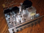
Help with a 1940's GE radio....
Now I'm trying to work on this radio for a friend, and I'm trying to figure out what the hell went wrong here.....
When I got it, there was a removed .05 uF 400 V cap that had burned, which I replaced. It extends between the on switch and one of the pins on the 35Z5, the same pin that the other end of the power cord goes to. There's also a burned resistor in that area. I'm looking at this damn set and thinking, well no wonder the damn thing fried, there's one .05 uF capacitor coupling both sides of the AC line!  It looks like it's got a fairly fresh power cord on it, so I'm wondering if this is actually right, or did somebody solder the cord on the wrong tube pin? It's a six tube set, and for some reason I can't find any schematics online that show, say, an all-american five set so that I can see where the pinouts on the 35Z5 actually go to. It just doesn't seem quite correct as it is 
__________________
"Restoring a tube TV is like going to war. A color one is like a land war in Asia." 
|
|
#2
02-06-2004, 10:32 AM
|
||||
|
||||
|
Hi Tim,
If you can get me a model number, and list the tubes, I can probably do some digging and get you some info in a day or three. clay
|
|
#3
02-06-2004, 08:24 PM
|
||||
|
||||
|
Can you find it here? http://archives.radioattic.com/archive_g1.htm
I have the Sams for the 221 - six tube AM / SW. Oh yeah - a pair of 6HA5s for ya too...
|
|
#4
02-06-2004, 10:51 PM
|
||||
|
||||
|
Thanks for the tube offer
 Don't need them any more though, I replaced them with 6HQ5s.... The set is a GE model L-600
__________________
"Restoring a tube TV is like going to war. A color one is like a land war in Asia."
|
|
#5
02-07-2004, 12:11 AM
|
|||
|
|||
|
Tim - I have the complete set of Beitman's manuals. The only GE model listed in the index is a 1950 model 600. These manuals cover all those old 'suicide box' radios so all you need to do is find one that matchs the tube complement and your good to go. Let me know.
|
| Audiokarma |
|
#6
02-07-2004, 03:13 AM
|
|||
|
|||
|
35z5 GE 1950. The 600 is incorrect as it was a battery powered model! Let me know the tubes if this don't do it.
|
|
#7
02-07-2004, 06:15 AM
|
||||
|
||||
|
Kamakiri said:
Quote:
The cap has to have a fairly high VAC rating as the induced instaneous voltage from the spark can be greater than 240 VAC, as I recall. Paul
__________________
People who think they know what they're doing are especially annoying to those of us who do!  My Gear My Gear
|
|
#8
02-07-2004, 11:58 AM
|
||||
|
||||
|
Hmmm.....so it's SUPPOSED to be there....interesting....
RocknRoll, that helped a LOT to clear things up. If you can email or post a complete schematic for such a set, that would be wonderful Tube compliment is 35Z5/35L6/12SQ7/12B7/12SA7/12B7
__________________
"Restoring a tube TV is like going to war. A color one is like a land war in Asia."
|
|
#9
02-07-2004, 02:14 PM
|
||||
|
||||
|
The GE 200 is similar to most of these six tube sets, though it uses a 115V pilot light - most use the #47 connected to the 35Z5 heater as shown above. I have a GE radio service manual, and found ZERO sets with the 12B7. But 12SG7 is the octal equivalent, if I remember correctly. They cheaped out on the front end and used a broadband RF amp instead of a third tuning gang. The model 220 I have uses the RF stage on on BCB - not on shortwave. I can email a bigger schematic if you need it.
|
|
#10
02-07-2004, 05:44 PM
|
|||
|
|||
|
This is what I found - The 12B7 is the same as 12SK7 except the socket and wiring. They are remote cutoff pentodes (used as RF/IF amplifiers or biased detectors in AC/DC radio receivers). The wiring and socket is different so one would have to rewire the socket to sub one for the other. I have some other schematics that use the 35Z5/35L6/12SQ7/12SK7/12SA7/12SK7 and the pinouts for 12B7 and 12SK7 can be found at the NJ7P Tube Database.
|
| Audiokarma |
|
#11
02-07-2004, 08:09 PM
|
||||
|
||||
|
Here ya go...
Here's the schematic for a GE L-600:
http://www.nostalgiaair.org/Resources/170/M0008170.htm There definitely is supposed to be a cap connected across the AC line, after the switch. It is necessary to minimize hum modulation of strong stations. The recommended replacement for safety reasons is a capacitor type rated for X or Y service, which will not catch fire if it shorts out. Courtesy of www.antiqueradios.com Hope this helps, Clay
|
|
#12
02-07-2004, 08:25 PM
|
|||
|
|||
|
Right on Fisherdude! That's the exact schematic. Good luck with the repair Tim.
|
 |
| Thread Tools | |
| Display Modes | |
|
|


 Linear Mode

