
|
|
|
|
|
#1
 05-23-2012, 12:52 AM
|
||||
|
||||
|
I hauled out my trusty old analog Triplett meter. The primary measures lower, if anything -- 400 ohms, give or take a couple. This is measuring from pin 1 of the VOT to test point 33 (275V source) in Sams.
The 100K/1W resistor (R60) is new and it measures 100K. I just remembered that my BK 1077B Analyst can provide a vertical plate drive signal. (I need to use that thing more often!) Tomorrow, I'll pull the VOT and see what happens with that signal. Regards, Phil Nelson 
|
|
#2
05-23-2012, 11:01 AM
|
|||
|
|||
|
Quote:
 I was fixing to suggest what Don L just suggested.. drive the output stage with AC. I was fixing to suggest what Don L just suggested.. drive the output stage with AC.
|
|
#3
05-23-2012, 11:54 AM
|
||||
|
||||
|
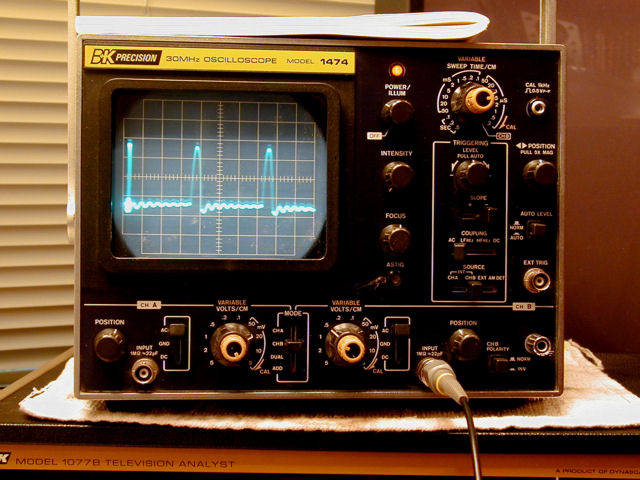
OK, the vertical plate drive signal from the 1077B looks like this:
 I removed the 6DR7 vertical output tube and injected the Analyst's vertical plate drive signal on pin 1. Here, the 1077B's Amplitude control is set about midway: 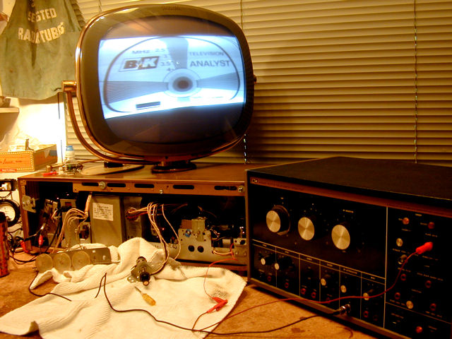 The height's about the same as before, with linearity very compressed toward the bottom. Cranking up the Amplitude control nearly fills the screen: 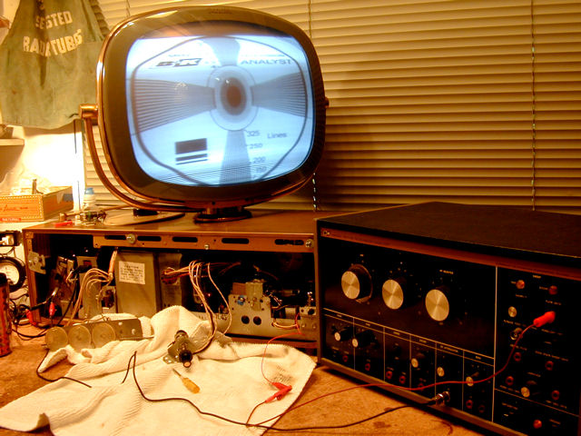 Phil Nelson
|
|
#4
05-23-2012, 02:21 PM
|
||||
|
||||
|
Phil, can your Analyst generate a signal to inject on the grid of the vertical output tube? Reason I ask, is that you still could have shorted turns on the vertical output transformer, and turing up the Analyst output would cover it up, sort of speak. The sam's says "do not Measure" so you don't know what the amplitude of the plate waveform should be. But the grid drive is shown. But it's inverted compared to the plate's, as you'd expect. If your analyist can make a grid waveform, dial in the amplitude, and disconnect the coupling cap C42 from the vert osc circuit and inject it via that cap to the output triode grid there. And see if the height is good.
__________________

|
|
#8
05-23-2012, 03:24 PM
|
|||
|
|||
|
It also looks like it is borrowing some neg bias from the horz out grid circuit. I would check R58 and R59 which makes up a voltage divider for the bias and also scope the grid of the 6DR7 pin 2-3. sometimes the neg voltages at the pins can be misleading esp if that bias supply is goofed up due to a faulty divider network (R58/R59). oh and check C50 the .22 cap that looks like it filters that bias supply.
|
 |
|
|


 Hybrid Mode
