
|
|
|
#151
 06-23-2019, 05:09 PM
|
||||
|
||||
|
Hey Mike,
I think you mean the beam positioning magnets on the CRT neck. Hopefully Steve McVoy has some somewhere. These photos from my CT-100 for reference for anyone viewing this post: -Steve D,
__________________
Please visit my CT-100, CTC-5, vintage color tv site: http://www.wtv-zone.com/Stevetek/ 
|
|
#152
06-23-2019, 05:17 PM
|
||||
|
||||
|
Steve, I will check with Mike on that.
He was describing a 6-32 thread about 2 inches long. I found something here: https://www.mscdirect.com/product/details/04891347
|
|
#153
06-24-2019, 11:38 AM
|
||||
|
||||
|
This is the part we need, a magnetic 6-32 thread “screw” for static convergence. It is one of three and I believe it is the same assembly as in the Steve D. Photos.
 Could this have been used in other RCA early color CRT’s? Any old dead CRT’s out there with this part? A search of the internet failed to find one. Last edited by etype2; 06-24-2019 at 11:49 AM.
|
|
#154
06-24-2019, 12:28 PM
|
|||
|
|||
|
I would think this kind of part could be made. The magnetic field isn't all that strong (about that of a magnetized screwdriver blade); I'd be more concerned with it being able to not demagnetize easily. This is part of the purity coil assembly, not the CRT itself. It's probably specific to the 15GP22 hardware.
__________________
Erich Loepke
|
|
#155
06-24-2019, 01:58 PM
|
||||
|
||||
|
Quote:
An attempt to generate this part was made a dozen years ago. It failed, however, because the magnetic field was much too weak. Notice also, that there is a screwdriver slot at each end. This is so the item can be removed and inserted backwards to utilize the opposite magnetic pole if and when needed. Good luck if you try to manufacture them. Donor sets are a protentional source; I had been fortunate to have located some that way. Pete Last edited by Pete Deksnis; 06-24-2019 at 02:04 PM.
|
| Audiokarma |
|
#156
06-24-2019, 02:37 PM
|
||||
|
||||
|
Quote:
__________________
Tom C. Zenith: The quality stays in EVEN after the name falls off! What I want. --> http://www.videokarma.org/showpost.p...62&postcount=4
|
|
#157
06-24-2019, 05:10 PM
|
||||
|
||||
|
I found this, but not sure it’s the right thread size. Also a question of strength. They are used in guitars. Perhaps the mount could be retreaded??
https://www.philadelphialuthiertools...ngth-set-of-6/
|
|
#158
07-02-2019, 10:58 AM
|
||||
|
||||
|
First Light From The 15GP22
UPDATE, JULY 1, 2019, DAY 331
FIRST LIGHT AND FLASH Author: According to the date codes, our 15GP22 was made between March 22-26, 1954. Our chassis was the 147TH produced. Tonight, 65 years after production we have first light from the 15GP22! YEA. Elation followed by a failure, a dreaded arc. Despite Mike’s efforts to control arcing, by pure luck, Mike caught on camera an arc inside the HV cage. Hmm, no arcing with the jigged CRT, but at first light, we get an arc. If you want to see the full resolution image of this event, tap on it to open the image carousel. Go here. https://visions4netjournal.com/westinghouse/ From Mike: “Greetings. I fired up the CRT this evening. The focus is good and I am able to adjust through both sides of focus with the control. Very happy with the results there. I cannot do any more with adjustments until the “new” magnet arrives but I am able to display all three guns, such as they are with poor purity. The purity should improve after I receive the magnet since I will then be able to set the center convergence properly. There is always interaction between purity and the center convergence adjustments so it is pointless to try any purity adjustments until the center convergence is at least “close”. This is by no means a representation of CRT quality as yet but it is certainly a milestone in the process. Near the end of my photography this evening, there was a high voltage arc. At the time, I was unable to determine its origin. It left the 1AX2 focus rectifier damaged so there was some kind of connection to that circuit at the time of the arc. As it turned out, the last picture I shot before the focus rectifier tube failed, was caught on camera. It was between the top of the 6BK4 high voltage regulator tube and the chassis nearby. It is obvious that I need to do more with controlling the arcing issues both inside the cage and outside. Picture #1 Red Picture #2 Green Picture #3 Blue Picture #4 The ARC Cheers, Mike” 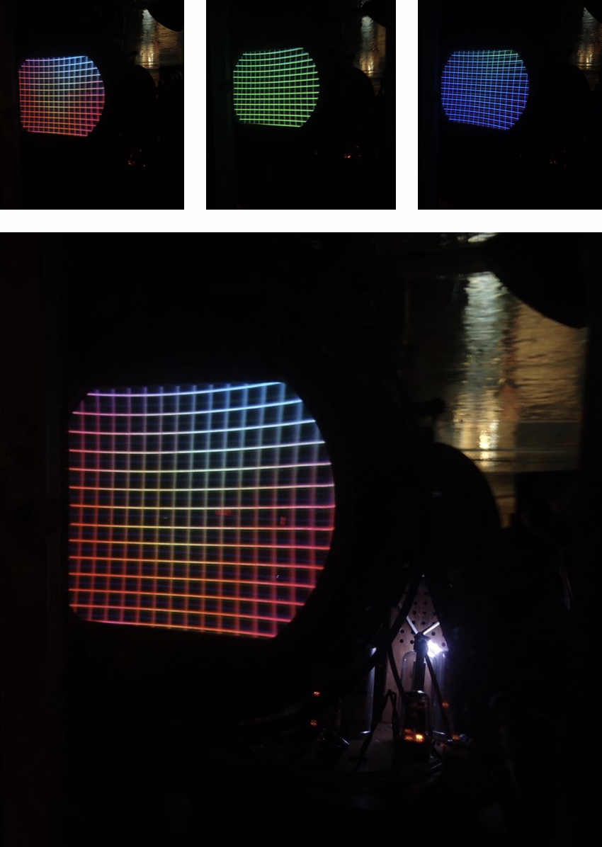
Last edited by etype2; 07-02-2019 at 11:04 AM.
|
|
#159
07-03-2019, 10:43 AM
|
||||
|
||||
|
An update regarding the arc event.
UPDATE, JULY 3, 2019, DAY 333 From Mike: “Hi Marshall. Short update here. The flash that I serundipidously caught occurred between the top of the HV regulator and one of the new electrolytic cans that I installed during the recap process. The cans come in all kinds of different “heights”. And I was careful to make sure that the clearances were OK for the crt to fit back in. But, I missed the fact that this one is just tall enough to creat a nice “spark gap” for the HV regulator. LOL! By the way, I meant to include that those images are MIRROR images. Anyway, the focus rectifier takes a large HV hit any time that there is a HV arc because it creats a “field flash” in the core of the flyback that is tranmitted to all of the rectifier tube filament wires. The HV rectifiers survive this field flash because they are rated for a much higher voltage than the focus rectifier is ratated for. The fix is easy. I will be adding insulation to all of the nearby electrolytic cans. I will also be adding a fiberglass barrier between the focus rectifier and the HV rectifiers. This will add some isolation between the two circuits. Westinghouse should have added this barrier anyway, in my opinion. I say that because of the close proximity of all those tubes to each other inside the HV cage. When on the jig, that tube and HV cable did not exist. I was running unregulated. More later, Regards, Mike” Last edited by etype2; 07-03-2019 at 11:40 AM.
|
|
#160
07-04-2019, 01:47 PM
|
||||
|
||||
|
Additional preventive measures.
From Mike: UPDATE, JULY 3, 2019, DAY 333 “Greetings. I spent the evening working on arc control. The arc that took place during the recent pictures was a result of the newly installed electrolytic capacitor in close proximity to the top of the H.V. regulator tube. I have done some work this evening in several parts of the HV system in an effort to avoid any more arcing. Pix #1 The 6BK4 HV regulator showing the nearby capacitor which is taller than the original. It is too close to the top of the tube which has 20 KV or more on the cap. Pix #2 Insulating tape installed on tops and sides of nearby capacitors. I have installed electronic lacing tape to keep the tape from coming loose. Pix #3 The 6BK4 reinstalled. Pix #4 The same insulation on the HV rectifiers with the lacing tape. Pix #5 The barrier that I made from insulation material to keep the focus rectifier voltages separate from the HV rectifier voltages. Westinghouse should have installed this barrier in the original design, in my opinion. Pix #6 The barrier installed. Still waiting for the magnet, but I am ready. Regards, Mike” Go here for full size images. https://visions4netjournal.com/westinghouse/ 
|
| Audiokarma |
|
#161
07-17-2019, 05:10 AM
|
||||
|
||||
|
UPDATE, JULY 16, 2019, DAY 346
From Mike: “Hi Marshall. Well, we finished the trip yesterday. So, now back to business here. I have been working on the convergence. The pot that I installed in the high voltage cage is not in proper range. This is no surprise since the new pot had some resistances built in to it. This required some calculations to make it come out right. One of the things that makes it tricky is the design by Westinghouse. The series resistance that makes up the resistance divider network for the pot is also the current limiting resistance for the high voltage regulator. So, the current through that network needs to be maintained in order for the high voltage regulator to work properly, and at the same time, the voltage selection by the pot needs to provide the proper range for the convergence grid in the crt. The range for the original pot was 50 megohms. The range on the new pot is roughly 22 megohms. So, I need to go back in to the high voltage cage and change some values and the work inside there is tight and tricky. But I am getting close. This work is for the center convergence only. I do not yet know what lies ahead for the edges. This has to come first. Here we go! Regards, Mike”
|
|
#162
07-19-2019, 12:46 PM
|
||||
|
||||
|
UPDATE, JULY 18, 2019, DAY 348
From Mike: I have made center convergence! YAY! The crt is not the best and the red is definitely weak compared to the green and blue. The blue is the strongest. I have not achieved good purity yet but I am still working on that. The purity control is all the way to one end and I may have to do some circuit modifications to get it in to a better range. I will be sending photos and data pictures of the succsessful center convergence later. But for now, I will send pictures of a POP and SMOKE that happened tonight. This may very well be a good commercial for Depends. It got my attention when it happened. I was merrily going along, doing adjustments and evaluating things when KABLOOEE. Then SMOKE from the rear of the chassis. The good news is, it is not disastrous. One of the AC line capacitors let go and exploded. These rarely ever give any trouble. But this one did. So I will be replacing both of them. They are mainly installed for line interference. Marshall, you are probably very glad that this did not happen at your house, and so am I. Onward! Author: Troublesome little bugger aint it. Go here for full size images: https://visions4netjournal.com/westinghouse/ 
|
|
#163
07-19-2019, 04:21 PM
|
||||
|
||||
|
If it uses the same purity coil as the CT100 then you have to both adjust the coil ring and adjust the purity control together to achieve purity.
Most original line bypass caps in tube sets are paper caps leaving them in circuit in any set you are fixing for a customer is a TERRIBLE practice in my book...worst case scenario it can become a fire Hazzard...Not something I want to be responsible for handing someone.
__________________
Tom C. Zenith: The quality stays in EVEN after the name falls off! What I want. --> http://www.videokarma.org/showpost.p...62&postcount=4
|
|
#164
07-20-2019, 01:37 PM
|
||||
|
||||
|
UPDATE, JULY 19, 2019, DAY 349
From Mike: Hi Marshall. I replaced the AC line capacitors tonight, and I also did some troubleshooting of the edge convergence issues. One thing that needed to be addressed was that one of the phase adjust coils was sloppy in its mounting to the chassis. So, JB weld epoxy has been applied and by tomorrow that coil will be rock solid in its mount. More troubleshooting will be required in order to find the real problem. I also spent some time building an adapter socket for the crt tester. I used the 15GP22 socket that was removed from this chassis in order to build it. It worked fine, and it tells an interesting story. I left the test going for a half an hour in order to give it a good warm up. Keep in mind that when I tested the crt last year, I did not give this kind of warm up time. The idea at the time was to simply evaluate the crt as working or not. This time, the test is more conclusive. Last years numbers: Red .825 Todays numbers 1.2 Last years numbers: Green .6 Todays numbers .8 Last years numbers: Blue .9 Todays numbers 1.75 (almost doubled) So, YES, the blue is much stronger now than it was before. And, I am a bit concerned about the numbers on Red and Green. The photos are: #1 The crt test #2 JB weld epoxy on the coil #3 The new caps on the AC line. Author: Better news about the gun strength, happy about that although the green is marginal. The cap that exploded was a silver mica type. Full size images here: https://visions4netjournal.com/westi...-carousel-9899 
|
|
#165
07-20-2019, 02:32 PM
|
||||
|
||||
|
Quote:
__________________
Tom C. Zenith: The quality stays in EVEN after the name falls off! What I want. --> http://www.videokarma.org/showpost.p...62&postcount=4 Last edited by Electronic M; 07-20-2019 at 02:35 PM.
|
| Audiokarma |
 |
|
|


 Personal website dedicated to Vintage Television


 Linear Mode

