
|
|
|
#226
 01-09-2011, 09:50 PM
|
||||
|
||||
|
Quote:

|
|
#227
01-13-2011, 10:53 PM
|
|||
|
|||
|
I find it interesting that on most of these restoration projects I keep reading “Recap Recap Recap”. The truth is if you have a vintage electrolytic that shows no leakage (infinite DC resistance) and ESRs’ (electronic series resistance or low AC resistance) good it will likely out last any attempt to stuff a bunch of small electrolytics in series in the old can to obtain the proper operating voltage. Yes they must be brought up SLOWLY to repolarize them. The critical ones are the deep cycling high voltage differential coupling caps. These are the ones that will eat your lunch and cost you flyback transformers.
One I have not seen mentioned is the high voltage rectifier. I have more than one crapy little $3.00 3A3 or 3AT2 eat a $60.00 flyback transformer. If the thing has any significant Edison effect on the glass replace it. Not a tube tester in the world will catch it and it will likely leak or short while your out of the room leaving you with a HV cage full of goo. Hope this helps. Good luck. Doogie Last edited by doogie812; 01-13-2011 at 10:54 PM. Reason: missing word
|
|
#228
01-14-2011, 09:16 AM
|
||||
|
||||
|
Quote:
But the vast majority of them will not show infinite resistance nor have decent ESR readings, we know this from experience. I will never trust a vintage set to a 60 year old cap, just as a matter of good practice. You may take your own chances as you see fit. As you already said, itmight cost you more than the price of a cap when it does god bad... Quote:
__________________
Evolution... 
|
|
#229
01-14-2011, 10:19 AM
|
|||
|
|||
|
Quote:
Quote:
Frankly, never heard of stuffing a bunch of small ones in series in the old can. "Edison effect" probably refers to darkening of the glass, which doesn't necessarily imply the tube is bad. But if it runs 'way hot to the touch after a few minutes, it would likely be on the verge of failing. That's the old school "life test" of a HV rect.  Bill(oc) Bill(oc)
|
|
#230
01-14-2011, 07:56 PM
|
||||
|
||||
|
All tubes run hot to the touch, I use an infrared thermometer for getting actual temp readings but even that's not perfect since reflective surfaces throw it off some. Darkening of glass (though not mentioned here) doesn't mean anything either, it's just what happens after a lot of electron bombardment.
__________________
Evolution...
|
| Audiokarma |
|
#232
05-26-2013, 03:01 PM
|
||||
|
||||
|
Reviving this thread because...
Someone sold me a working 21AXP22A! A GE-branded rebuild NOS in the box, measures in the middle green on all three guns on the RCA tester. Here are the first pix after a day and a half of removing the "temporary" makeshift mount and 21FBP22 glass tube and reinstalling the metal tube support hardware. Plus about 40 minutes of roughing it in. The SAMS bias set up procedure just doesn't seem to work right on this set. couldn't get any red at all until turning up the screen setting. Also, supposed to start with 130 volts red K-G, but can get 110 max. I will try the RCA procedure, which is somewhat different. This set is still weak on luma drive, even with AGC cranked, so maybe I have to do something in the IF (replace tubes?). Replacing video outputs never cured it. Images look much brighter in these shots than they really are. 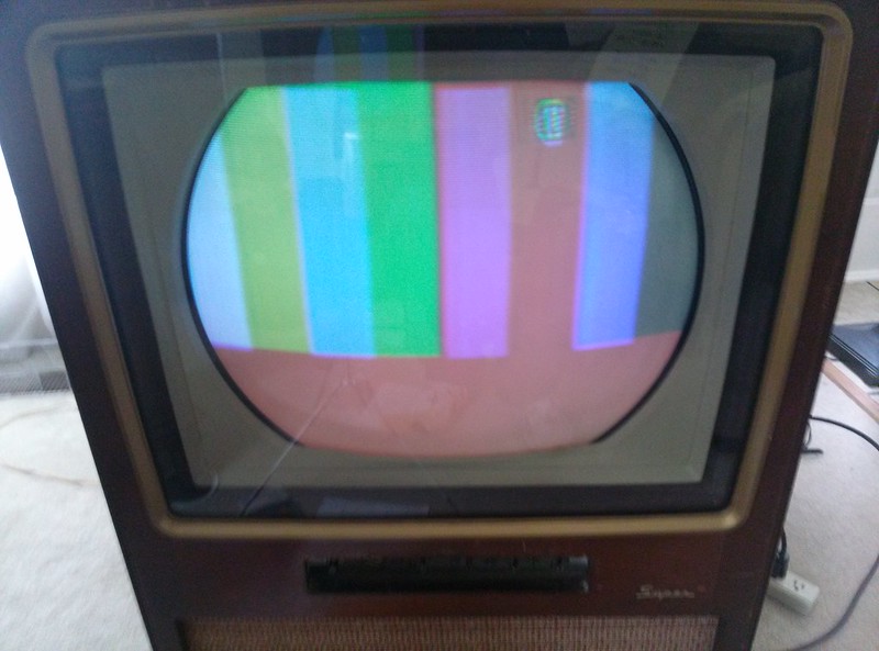 003 by old_tv_nut, on Flickr 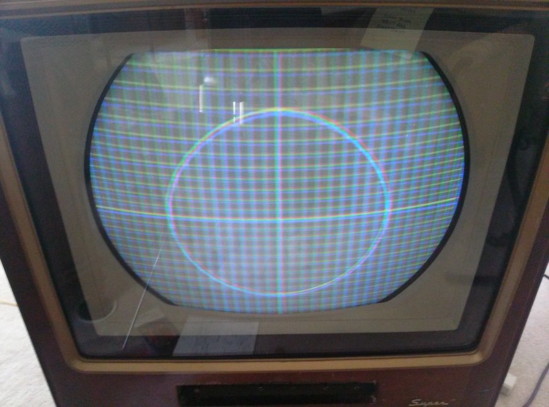 First rough convergence with 21AXP22A by old_tv_nut, on Flickr
|
|
#233
05-26-2013, 03:07 PM
|
||||
|
||||
|
I forgot to mention - yoke seems to want to be max forward for purity, would be nicer if it had some room to go beyond optimum point. Anyone who has worked with CTC-5, what is your experience?
(Of course, this may change, for all I know, after successive approximations to convergence etc.)
|
|
#237
05-26-2013, 08:13 PM
|
||||
|
||||
|
Quote:
How good is the purity: do you reach the optimum purity pointwithf the yoke forward? And also, what does the HV measure?
|
|
#238
05-26-2013, 10:02 PM
|
||||
|
||||
|
Quote:
Haven't measured the HV - it measured on spec before. (The spec for this chassis is rather low - I forget what exactly.) I do recall, however that the luma on the cathodes was low (compared to the chroma demod outputs on the grids) and has been since I got the set. Changing out the video output did not seem to help. I think a reasonable design should be able to generate luma drive at least half the p-p voltage of the color difference p-p on the grids. The chassis is capable of color difference p-p much greater than 2x luma p-p. Time to get out the scope and verify what I recall. One problem is not having any service info showing waveforms with full color bars. The luma waveform with gated rainbow input is meaningless, so I have no idea if I'm getting the expected amplitude - but it seems low to me compared to the range that is available from the color difference. By the way, I have solved a mystery - I noticed that a full red field (from a test signal, not from shorting the grids) looks washed out. If I am reading the schematic right, the color difference outputs are only 75% DC coupled to the grids. This, combined with about 75% DC coupling in the luma, causes a full red field to be washed out when color level is correct on color bars. I can't figure out why the designers reduced the DC coupling in the color difference. There have never been white balance problems in broadcasts that this might reduce. If they were worried about DC drifts in the demods, a 25% reduction would not be enough to fix it. Later sets used the RCA three-triode matrix amplifiers with "X-Y" demods, and the matrix amp circuit had built in DC restoration by drawing grid current when the negative blanking pulse was applied to the cathodes, so demod drift was not a problem. Just another way the CTC-5 super chassis is weird and inferior. If I convince myself I am right, I will try cutting out three .01 uF caps that I believe cause the 75% DC coupling in the color difference signals. Another by-the-way: I couldn't follow the RCA gray scale set-up procedure, since it assumes there is no R background control and you set G and B backgrounds to match. This later chassis has background controls in all three colors. So, I tried modifying the procedure to a sort of hybrid of the RCA and SAMS. It looks better, but probably is not optimum. It probably won't be optimum until I can get more luma drive.
|
|
#239
05-26-2013, 10:11 PM
|
||||
|
||||
|
Quote:
|
|
#240
05-27-2013, 09:54 AM
|
||||
|
||||
|
Quote:
....... just warms my heart , seein a squirrel complementing a nut  And on a serious note , Congrats from me too on your new tube ! And on a serious note , Congrats from me too on your new tube !
|
| Audiokarma |
 |
|
|


 Linear Mode

