
|
|
|
#1
 12-02-2016, 06:31 PM
|
||||
|
||||
|
Using an op-amp "rectifier" as an AM detector
Using a high speed op-amp, in this case a HA2525, I built a "rectifier" circuit as an AM detector. Idea is that it should be more linear than an ordinary diode.
This particular op-amp circuit outputs the negative going parts of the RF carrier and the amplitude modulation. Instead of a curved diode knee, this circuit would do a much sharper knee, thus better detection of weak signals and also strong signals (better audio fidelity on music). Like this (though the polarities are different)  vs for a diode 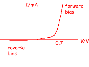 We also avoid the effects of the AGC cap backfeeding the detector. The RC circuits fed by the op-amp's output filters out the RF part of the rectified waveform to get audio, and AGC voltage.
__________________


|
|
#3
12-03-2016, 09:18 AM
|
||||
|
||||
|
I think the main advantage of the good linearity is for low distortion at high percent modulation, not so important for handling strong signals. Some advantage for weak signals (assuming not enough RF/IF gain and AGC action to get full output at the radio's noise floor).
An elegant high-fidelity circuit.
|
|
#5
12-03-2016, 03:48 PM
|
||||
|
||||
|
If the nominal voltage is close to zero, put the trimpot between two larger value resistors to limit the range. At the same time, I would reduce the values so the total on each side of the wiper is still about 50k, to prevent offset drift due to input bias current drift. So, maybe a 10K pot with 47k on each end?
|
| Audiokarma |
|
#6
12-03-2016, 08:52 PM
|
||||
|
||||
|
Quote:
__________________
Last edited by wa2ise; 12-03-2016 at 10:25 PM.
|
|
#7
12-05-2016, 08:01 AM
|
||||
|
||||
|
Reminds me of what Fluke uses to convert AC to DC in multimeters....
__________________
Brian USN RET (Avionics / Cal) CET- Consumer Repair and Avionics ('88) "Capacitor Cosmetologist since '79" When fuses go to work, they quit! Last edited by Findm-Keepm; 09-29-2017 at 06:39 PM.
|
|
#8
12-07-2016, 10:04 AM
|
||||
|
||||
|
I did some more work on it and made it a peak detector. I never much liked having to use trim pots, which usually means that the circuit isn't self bias correcting, and can easily get out of adjustment. Added a 3nF cap to the circuit output, and some resistance to the positive supply, here a 100K resistor. Also a 270K resistor to the + input of the op-amp, which also has a 910 ohm resistor to ground, used to minimise the error caused by the input bias current. Found that another resistance to the positive supply, a 270K resistor got the circuit in the sweet spot of detection. I think that these resistors are making up for the fact that my op-amp power supplies are not exactly the same absolute value voltages, and for the AGC line IF amp bias circuit. And it's not at all fussy, varying supply voltages doesn't mess it up. Substantially self biasing. I kept the 2nd diode, it acts like a catcher for the op-amp's output pin so it doesn't have to slew back so far when it comes time to rectify again .
__________________
|
 |
|
|


 Linear Mode

