
|
|
|
#181
 08-06-2019, 07:24 PM
|
|||
|
|||
|
About the only benefit to a copper plated chassis I can think of is it will be a better ground plane than plain steel, especially at RF. I really can't say how much of a difference it makes in reality since so many TVs were made with regular old steel and they worked fine.
__________________
Erich Loepke 
|
|
#182
08-06-2019, 07:50 PM
|
|||
|
|||
|
The "steel" chassis seemed to do an adequate job of shielding and routing the ground side of the circuits. RF might benefit some from the copper, but if that were the case, why do the whole chassis? Just do the tuner and maybe the IF strip.
|
|
#185
08-07-2019, 12:40 PM
|
||||
|
||||
|
Some makers switched between copper and cadmium plated steel chassis multiple times...it probably came down to a mix of engineering department preference VS accounting department thrift as to what would be used.
__________________
Tom C. Zenith: The quality stays in EVEN after the name falls off! What I want. --> http://www.videokarma.org/showpost.p...62&postcount=4
|
| Audiokarma |
|
#187
08-07-2019, 06:51 PM
|
||||
|
||||
|
Cadmium is surely the worst. CRT makers stopped using cadmium in phosphors when it became too difficult/costly to eliminate it completely from plant effluent.
|
|
#188
08-11-2019, 02:40 PM
|
||||
|
||||
|
First images on the Westy 15GP22
UPDATE, AUGUST 10, 2019, DAY 371
Hi Marshall. I am sending these pictures but I must say the images look a lot better than the pictures show. Not sure what’s going on with the images from the crt. Other images are fine. The focus is actually much better than the images show, and really not so grainy. Anyway, here goes. Also, I decided to install a fan on the power supply which is a fair distance from any magnetic interference for the crt. The 50 watt resistor heats things up a bit but it is necessary. The gain here is that we are not lighting up qty 2 5U4’s any more which is a big load taken away from the power transformer. (filaments) Pix #1 Temporary hookup of the crt wires during the installation of the 15GP22 tube. Pix #2 The hookup cleaned up properly with shrink wrap and proper color codes on the wiring. Pix #3 The power supply chassis showing the newly installed silicon rectifiers which I implemented into old 5U4 sockets from dead 5U4 tubes. And the newly installed 300 ohm 50 watt resistor and fan. Pix #4 The final circuit that worked well for the convergence pot new design. Pix #5,6,7 Images from antenna tv over the air that are actually better than the images show. Author: First impression, the images look brighter than expected. Picture #5 and #8 show diagonal banding artifacts from the camera. We also have a purity issue seen in the lower left hand portion of the screen on #5. Diagonal banding occurs when the camera is held in the portrait mode. Picture #6 shows a horizontal banding artifact in the lower half of the image, distorting the color. Sometimes the artifacts can be removed by adjusting the camera settings. Picture #7 looks to blue. These images came from less than an ideal source. Mike only wanted to show what we have achieved thus far. I agree with Mike that the images look out of focus and grainy. Mike has not adjusted the purity as yet and will continue working on the convergence. We have a way to go. This did not fit in the last email. It is pix #8 I believe. Onward to improve the convergence a bit. But we are getting close. The picture is very stable and no more arcing so far. Regards, Mike Author: I want to thank Steve McVoy for the 21 pin socket, John Folsom for the VCT and Dave Abramson for the spare convergence magnet. I strongly suggest viewers open this link to see full resolution images in the carousel. https://visions4netjournal.com/westi...-carousel-9954 
Last edited by etype2; 08-16-2019 at 02:20 PM.
|
|
#189
08-11-2019, 05:38 PM
|
|||
|
|||
|
Personally I think the CRT pictures look pretty good. I really don't think the 15GP22 will every give a really sharp picture just because the phosphor dots are relatively large for the screen size.
__________________
Erich Loepke
|
|
#190
08-12-2019, 07:38 AM
|
||||
|
||||
|
The dot pitch on the 15GP22 is adequate, but just barely. On my test pictures I really can't see any more actual detail on my current setup which displays the RGB that normally feeds the CT-100's grids on a pro grade Sony monitor of the same size than I
could on the 15GP22. It was just a bit grainier due to the dots. The picture I now see is almost perfect for I-Q demodulated NTSC. See the new thread I am starting for the exception.
|
| Audiokarma |
|
#191
08-12-2019, 08:08 AM
|
||||
|
||||
|
The 15GP22 has 585,000 dots. The 21AXP22 has 1,071,000 dots. That equates to 39,000 dots per inch on the 15GP22 and 51,000 dots per inch on the 21AXP22.
Last edited by etype2; 08-12-2019 at 08:16 AM.
|
|
#192
08-12-2019, 08:46 AM
|
||||
|
||||
|
What matters is dots per picture size so the
21AXP22 would win by a ratio = sqrt(1071/585) = 1.35, not a lot, but significant. This assumes the same mask shape, which is very close to true.
|
|
#193
08-14-2019, 11:42 AM
|
||||
|
||||
|
An update from Mike last night. The colors look close to SMPTE patterns. We are close. Mike plans to “cook” the set for the next three weeks and then home.
“Hi Marshall. I got this one with my phone camera. Not perfect, but OK. I messed around with the purity a bit and the spot is now in the upper left but much fainter. The best I seem to be able to do with it. Mike” 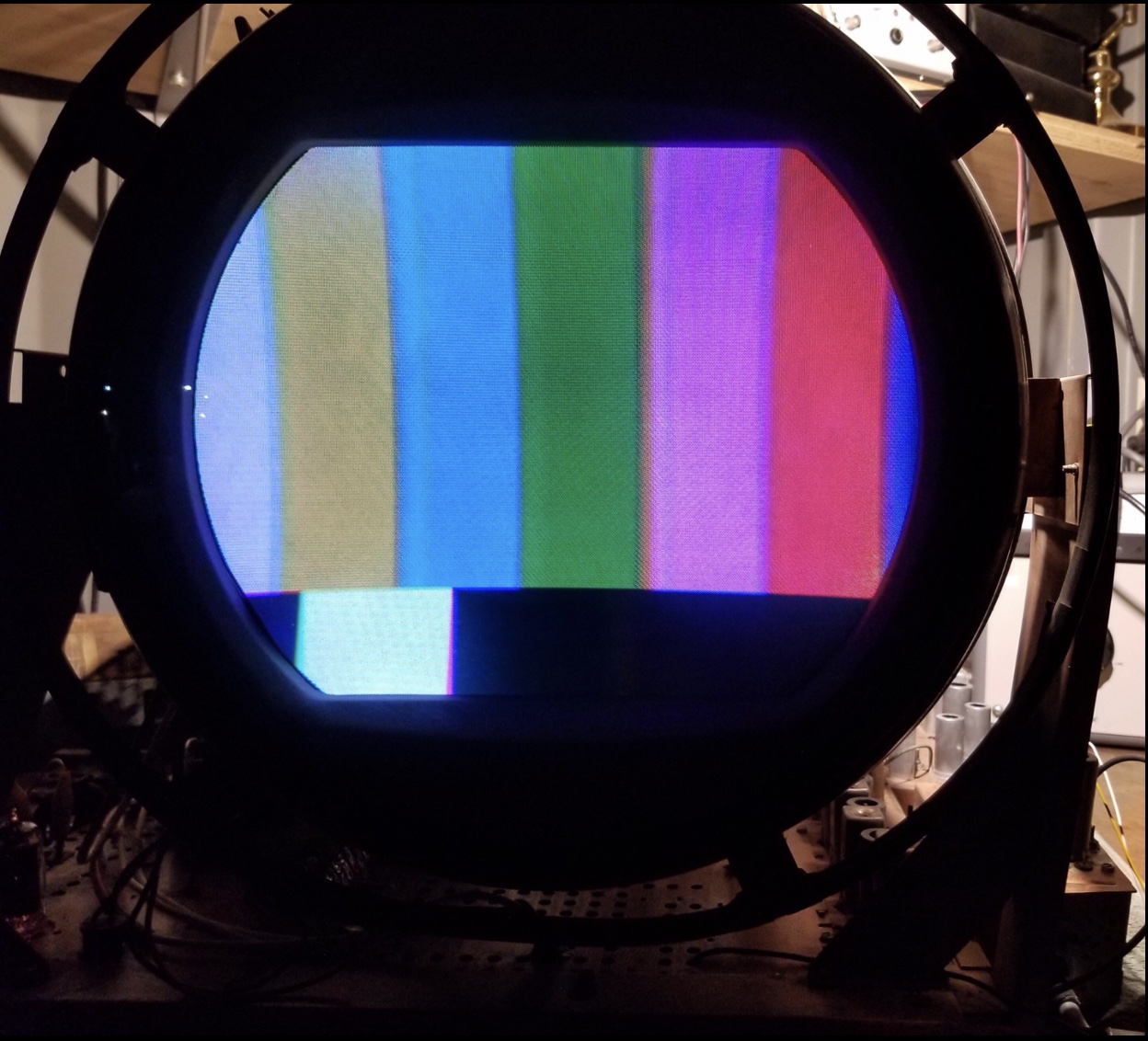
|
|
#194
08-14-2019, 12:26 PM
|
|||
|
|||
|
That color is looking real good! I keep having to tell myself the colors are not wrong since most of the color bars look different than what I am used to on regular sets. But just about every photo I have seen of 15GP22 color bars look the same, with the deeper green and somewhat muted yellow. These must be the intended NTSC colors in this case.
__________________
Erich Loepke
|
|
#195
08-14-2019, 01:42 PM
|
||||
|
||||
|
You can do a lot better than that on a 15GP22. The key is to not force it to be too bright. Be sure that you are never driving the red gun into grid current.
I did on my CT-100 when I first got it. The Westinghouse at the ETF has on occasion done much better. I need to look at what adjustments the Westinghouse has. To do it on my CT-100 I had to add one additional adjustment pot temporarily to get it right, the put in the correct matrix fixed resistor. I looked: the Westy has sufficient controls. But do note that the color matrix controls all interact, as the matrix resistors do not drive current into a virtual ground, as they would the the mixer tube were an inverting op-amp. The CT-100 does have feedback there so the interaction is less. Tweek until its right. The final criterion is looking at the screen through good color filters and/or looking at the dots on the screen through a magnifying glass to see that the "off" dots are off. Note that DC restoration is never perfect on these tube sets like it is on modern solid state ones. Finally ... be sure that AGC is set right so that there is no clipping of the composite video.
|
| Audiokarma |
 |
|
|


 Personal website dedicated to Vintage Television
 Linear Mode

