Videokarma.org

Go Back   Videokarma.org TV - Video - Vintage Television & Radio Forums > Early B&W and Projection TV

We appreciate your help

in keeping this site going.
Reply
 
Thread Tools Display Modes
  #76  
Old 12-11-2016, 08:45 AM
Crist Rigott Crist Rigott is offline
VideoKarma Member
 
Join Date: Oct 2015
Location: Waxahachie, TX
Posts: 1,506
Quote:
Originally Posted by WISCOJIM View Post
I'd measure the cap and see what it truly was, and match that.

.
That would be kinda hard, seeing it's been cut in half. anyways I don't have any way to measure it.
Reply With Quote
  #77  
Old 12-11-2016, 08:51 AM
kvflyer kvflyer is offline
VideoKarma Member
 
Join Date: Nov 2006
Location: Fernandina Beach, FL
Posts: 1,061
Quote:
Originally Posted by Crist Rigott View Post
After removing the cardboard cover, this is what I found:...
I was a bit taken back but decided that what I should use is what the schematic and parts list calls for.

What do you think?
That is quite normal. Capacitor manufacturers would often use a can that was already stamped and stuff whatever they needed into it when they knew they were going to put a cardboard sleeve around it. I have seen it several times.
Reply With Quote
  #78  
Old 12-11-2016, 08:58 AM
Crist Rigott Crist Rigott is offline
VideoKarma Member
 
Join Date: Oct 2015
Location: Waxahachie, TX
Posts: 1,506
Quote:
Originally Posted by kvflyer View Post
That is quite normal. Capacitor manufacturers would often use a can that was already stamped and stuff whatever they needed into it when they knew they were going to put a cardboard sleeve around it. I have seen it several times.
I was thinking along the same lines. Remember this cap has never been installed, it is a part of the kit.
Reply With Quote
  #79  
Old 12-11-2016, 11:43 AM
dieseljeep dieseljeep is offline
VideoKarma Member
 
Join Date: Jul 2010
Posts: 7,562
I restuff my cans in much the same way. The only thing different is, instead of the PVC pipe, I use the thin aluminum salvaged from a beverage can.
I cut the can apart with kitchen shears and roll the metal up as a sleave, then I use silicone sealant to hold it all together.
Reply With Quote
  #80  
Old 12-11-2016, 12:04 PM
dieseljeep dieseljeep is offline
VideoKarma Member
 
Join Date: Jul 2010
Posts: 7,562
Quote:
Originally Posted by WISCOJIM View Post
I'd measure the cap and see what it truly was, and match that.

.
I looks like they used more of those scrappy grab-bag parts.
The label made on a spirit duplicator shows some real class. Reminds me of school days, where some weekly tests were ran off on them.
The cap has a Sentinel part number from 1953.
I would use 22mfd for the 10, 47 for the 20 @250 volts and 100 @160 volts for the 100 section.
BTW, Is there any truth to the theory that operating too high of a voltage rated 'lytic on lower voltage, IE a 450 volt cap at 150 volts, that they never seem to form properly, or just another urban tale.
Reply With Quote
Audiokarma
  #81  
Old 12-11-2016, 01:38 PM
Kevin Kuehn's Avatar
Kevin Kuehn Kevin Kuehn is offline
Workin' Late Again
 
Join Date: Jan 2011
Location: WI
Posts: 3,824
Quote:
Originally Posted by dieseljeep View Post
BTW, Is there any truth to the theory that operating too high of a voltage rated 'lytic on lower voltage, IE a 450 volt cap at 150 volts, that they never seem to form properly, or just another urban tale.
I tend to think they form up good enough for whatever voltage they're operated at. Admittedly it's one of my armchair theories, but to the best of my knowledge I've never had a cap fail because it's been operated at too low of voltage.
Reply With Quote
  #82  
Old 12-11-2016, 04:07 PM
N2IXK's Avatar
N2IXK N2IXK is offline
Technohippie
 
Join Date: Apr 2011
Location: Sittin' on the "Group W" bench...
Posts: 801
Quote:
Originally Posted by kvflyer View Post
That is quite normal. Capacitor manufacturers would often use a can that was already stamped and stuff whatever they needed into it when they knew they were going to put a cardboard sleeve around it. I have seen it several times.
I'll second this. And it wasn't just budget manufacturers or short runs like training kits that they ended up in, either. Have seen them as OEM parts in RCA and DuMont sets, at least. Real obvious stuff like a 4 section cap that is stamped for a single section cap on the can itself.

Just the cap manufacturer "reclaiming" perfectly usable scrap from a previous production run, and using it where it presumably wouldn't be noticed.
Reply With Quote
  #83  
Old 12-11-2016, 05:29 PM
Crist Rigott Crist Rigott is offline
VideoKarma Member
 
Join Date: Oct 2015
Location: Waxahachie, TX
Posts: 1,506
Quote:
Originally Posted by N2IXK View Post
I'll second this. And it wasn't just budget manufacturers or short runs like training kits that they ended up in, either. Have seen them as OEM parts in RCA and DuMont sets, at least. Real obvious stuff like a 4 section cap that is stamped for a single section cap on the can itself.

Just the cap manufacturer "reclaiming" perfectly usable scrap from a previous production run, and using it where it presumably wouldn't be noticed.
Yes, I agree.
Reply With Quote
  #84  
Old 12-11-2016, 05:34 PM
Crist Rigott Crist Rigott is offline
VideoKarma Member
 
Join Date: Oct 2015
Location: Waxahachie, TX
Posts: 1,506
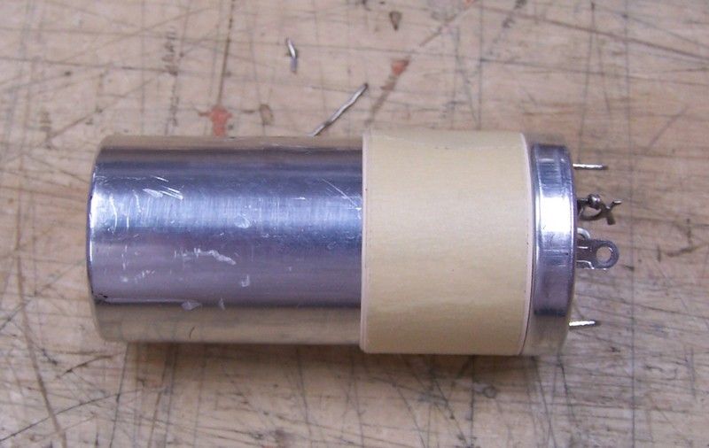
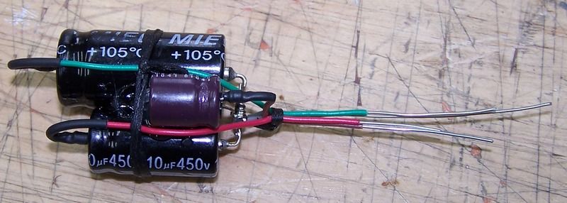
Here is how I re-stuffed the E-Caps. Once the epoxy is dried, I attached some wires to each E-Caps, then used some hot glue to glue them together. I routed the wires together and secured them with some string tie. Then they were inserted through the hole and hot glued into place. Then the wires are soldered to each terminal.

I then slid on the can and fixed it into place with some clear tape. Then I wanted to increase the diameter of the can because the cardboard tube is a larger diameter that matches the base. This was done so when the E-Cap is inserted into the clamp, the cardboard tube is not crushed. I used some masking tape and manilla folder stock.

Then the tube is slid over the whole assembly. No glue is required here because of the clamp method of mounting.

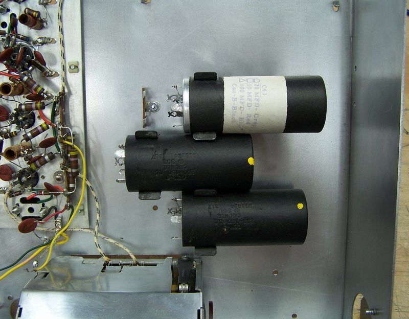
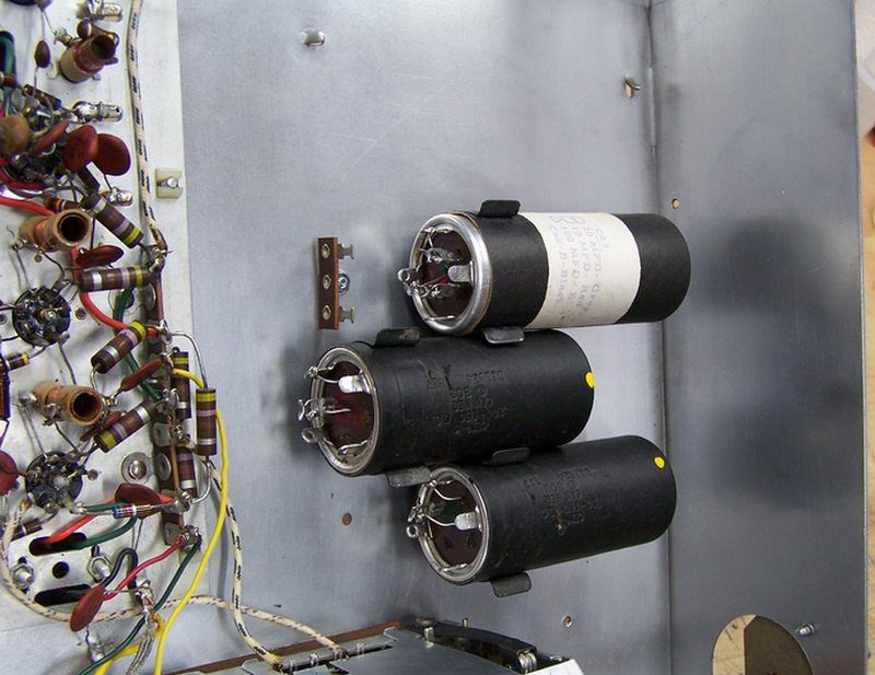
The E-Caps were then inserted into their proper clamps. I did re-position TB20 by turning it 90 degrees to give me more room between TB20 and C43.


Reply With Quote
  #85  
Old 12-11-2016, 05:37 PM
Crist Rigott Crist Rigott is offline
VideoKarma Member
 
Join Date: Oct 2015
Location: Waxahachie, TX
Posts: 1,506
I do think that completes all the "prep" work I wanted to do before assembling the kit.

I still need some caps which are on order and should be here this coming week.
Reply With Quote
Audiokarma
  #86  
Old 12-11-2016, 05:51 PM
N2IXK's Avatar
N2IXK N2IXK is offline
Technohippie
 
Join Date: Apr 2011
Location: Sittin' on the "Group W" bench...
Posts: 801
It is kind of interesting that the kit came with all the tube sockets and terminal strips riveted in place. With Heathkits and Eico kits, the mechanical assembly was left to the kit builder, using screws and nuts, rather than rivets.

On Eico gear, you can usually identify the factory wired units by the riveted components, vs. the screws used on the kit units.
Reply With Quote
  #87  
Old 12-11-2016, 06:54 PM
Crist Rigott Crist Rigott is offline
VideoKarma Member
 
Join Date: Oct 2015
Location: Waxahachie, TX
Posts: 1,506
Quote:
Originally Posted by N2IXK View Post
It is kind of interesting that the kit came with all the tube sockets and terminal strips riveted in place. With Heathkits and Eico kits, the mechanical assembly was left to the kit builder, using screws and nuts, rather than rivets.

On Eico gear, you can usually identify the factory wired units by the riveted components, vs. the screws used on the kit units.
Yeah, on this one, to clean the bottom of the chassis better, I drilled out the riveted terminal strips, then used some 4-40 hardware to bolt them back on.
Reply With Quote
  #88  
Old 12-11-2016, 11:23 PM
Crist Rigott Crist Rigott is offline
VideoKarma Member
 
Join Date: Oct 2015
Location: Waxahachie, TX
Posts: 1,506
I'm looking at the 115vac mains connection to the chassis.

Now I have to mention that the IF strip, Tuner, and all B- is floating above the chassis. The IF Strip and Tuner are mounted to the chassis using nylon "clip" nuts and the metal plate of the IF Strip and all the metal of the Tuner does not show continuity to the chassis.

Here is a photo of the mains power part of the schematic. Resistor R58, 1 meg, goes from the "switched" side to the chassis. This is the only connection that I can see where the chassis is connected to the mains. C54 will be a Y2 safety cap, and C52 will be a Y2 safety cap. There are 2 more caps one from the IF Strip metal plate and one from the Tuner chassis that goes to the chassis. I'm guessing that these need to be Y2 safety caps too. In the schematic you can see one of them (C57 from the Tuner chassis to the chassis) in the upper R/H corner.
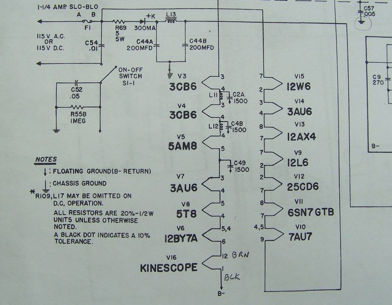


I've never worked on a hot chassis before, so my question is should I wire the hot leg to the switch and the neutral through the fuse and onto the rest of the circuit? Seeing it is AC does it really matter? Should I reconfigure the wiring to switch the hot leg and have it going to the fuse and onto the rest of the circuit?

I do plan on using a polarized plug for the power cord. I won't be using the provided interlock cord though. Also I'll be using my isolation transformer with this chassis.

Last edited by Crist Rigott; 12-11-2016 at 11:43 PM.
Reply With Quote
  #89  
Old 12-12-2016, 05:45 AM
N2IXK's Avatar
N2IXK N2IXK is offline
Technohippie
 
Join Date: Apr 2011
Location: Sittin' on the "Group W" bench...
Posts: 801
Proper practice would be to wire the neutral side DIRECTLY to B-, and run the hot side first to the fuse, then through the switch.

Yes, all the caps from B- to chassis need to be mains-rated types.
Reply With Quote
  #90  
Old 12-12-2016, 04:50 PM
Crist Rigott Crist Rigott is offline
VideoKarma Member
 
Join Date: Oct 2015
Location: Waxahachie, TX
Posts: 1,506
Here is another thought that I had. Would this TV benefit from a thermistor in the filament string? My mains are 122vac while the filament string adds up to 115vac.

Another question. In the tube data sheets they say the heater is surge is minimized during warm up. Most of the tube data sheet said this. What do they mean? Maybe I don't need a thermistor?

Last edited by Crist Rigott; 12-12-2016 at 06:21 PM.
Reply With Quote
Audiokarma
Reply


Posting Rules
You may not post new threads
You may not post replies
You may not post attachments
You may not edit your posts

BB code is On
Smilies are On
[IMG] code is On
HTML code is Off

Forum Jump


All times are GMT -5. The time now is 12:02 AM.


Powered by vBulletin® Version 3.8.4
Copyright ©2000 - 2024, Jelsoft Enterprises Ltd.
©Copyright 2012 VideoKarma.org, All rights reserved.