
 |
|
#91
|
||||
|
||||
|
They probably selected "controlled warm up" tubes (octals often had a 'GTA' or 'GTB' post fix to identify that IIRC) for the design...Controlled warm up tubes would warm up in sync IIRC by sensing heater current so no tube would be momentarily taking a bigger portion of the voltage than designed.
A thermistor or dropping resistor would not hurt, but is not essential either IMO.
__________________
Tom C. Zenith: The quality stays in EVEN after the name falls off! What I want. --> http://www.videokarma.org/showpost.p...62&postcount=4 |
|
#92
|
|||
|
|||
|
Quote:
|
|
#93
|
|||
|
|||
|
I have decided to wire the TV like the kits shows. I will use safety caps where needed and I replaced the Selenium rectifier with a 2 lug terminal strip and a 1N4007 diode. On the schematic, there looks like 300ma by the selenium rectifier. I'm guessing that either this is the rating of the rectifier or the total current draw through the rectifier. In any case a 1 amp diode exceeds those numbers by a factor of 3.
I started step 1 (Power Supply and Filament) yesterday (Monday) and finished it today (Tuesday). Some observations are in order. All-in-all the step by step instructions and the pictorial work very well and the steps are in a logical order. For instance, to wire the filament string, you start at the fuse holder then wire the first tube as in the schematic (V15), then the next wire goes to V14 and so down the filament string. Working with 20awg solid hook-up wire can be a bit trying especially on the small 7 pin tube sockets. Those terminals are fragile! No mishaps yet. The wire lengths given is the step-by-step are for the most part fairly accurate. There were about 6 wires where I changed the length by maybe an inch. One wire was 2 inches too long. So far this was the only big error in wire lengths. I'd rather have it long than too short. Of course I trimmed the wire to a more reasonable length. I routed the wires per the instruction sheet all within reason. For R69 a 5 Ohm 5W resistor just at the minus side of the rectifier I used a 22 Ohm 10W sand resistor simply because that's what I had. Once the TV is up and running and with the 122Vac line voltage applied, then the resistor will be substituted for the correct value and wattage. Most likely be a gold chassis mount type resistor. You can see this resistor in the lower left corner of the chassis along with C54, the Safety cap. Oh, yeah, I labeled each terminal strip, tube, and pot with small pieces of masking tape to help to ID the component location. 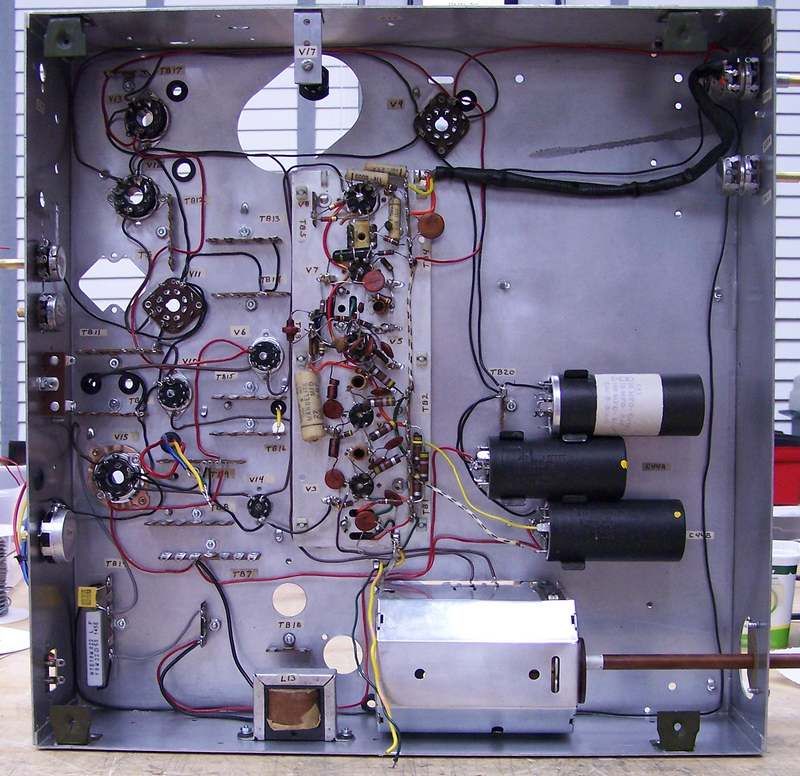
Last edited by Crist Rigott; 12-17-2016 at 09:27 AM. |
|
#94
|
|||
|
|||
|
Quote:
It's a rather large undertaking for a person without the restoration, kit building and troubleshooting skills that many of us have on this forum. 
|
|
#95
|
|||
|
|||
|
Well with the talent and help of this forum, I'm sure I'll be successful.
|
| Audiokarma |
|
#96
|
|||
|
|||
|
I started on step 2 today. I came across something that I decided to change. It was a terminal strip on the IF Strip. It looks like they didn't have the correct one so they made one form 2 others. They took 2 3 position strips and soldered them together.
Also some of the terminals needed "help" as in they were full and I needed to add at least 1 wire to it. So I had the correct terminal strip on hand so I replaced the made up one. While I have the components removed from the terminal strip, the resistors and caps will be replaced. 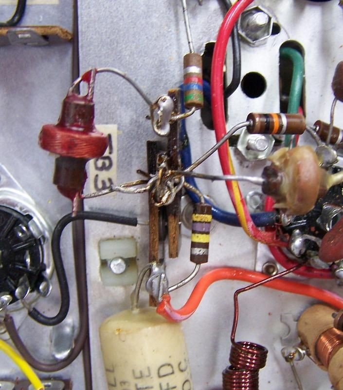 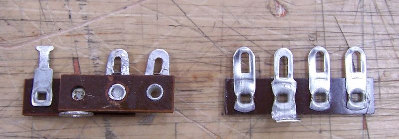 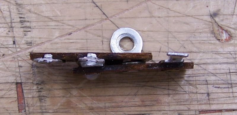 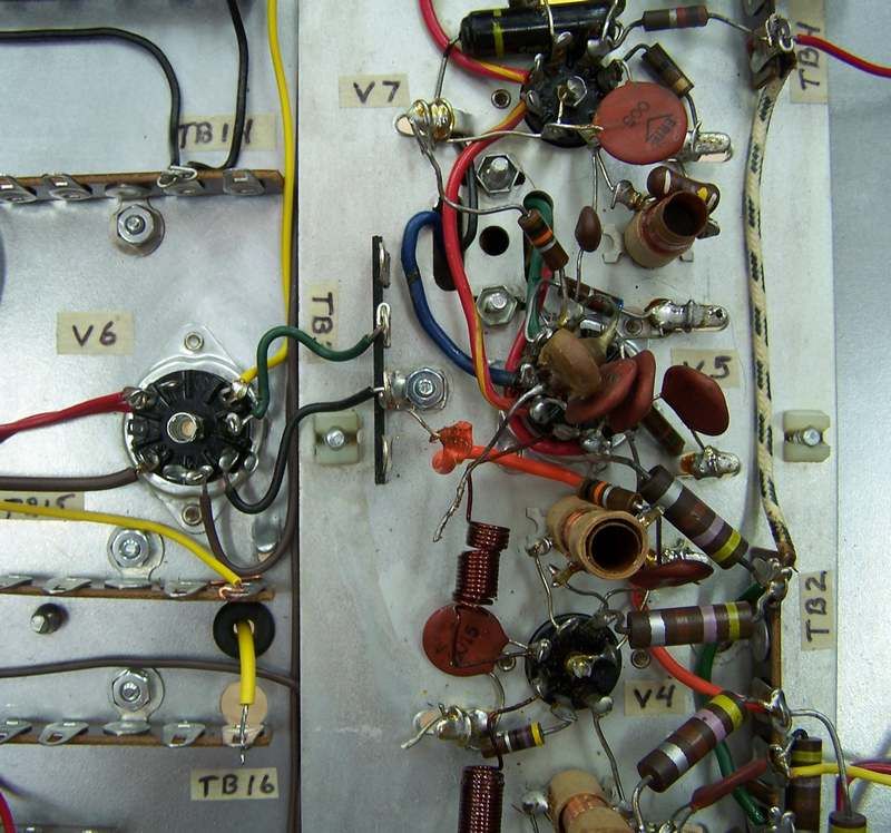
|
|
#97
|
|||
|
|||
|
When changing out that terminal strip, I decided to replace the components attached to it. When 1 lead went to a tube socket or ground and there was another component attached there as well it got replaced. I also changed the filament wires to my brown color code.
When I replaced the caps and resistors, I checked their values. Most were very close to what they were supposed to be. All the cap values checked good but a couple of the resistors were out of tolerance. As my usual practice all film and electrolytic caps get replaced. With this done on the IF strip , I'm ready to resume with instruction sheet 2. 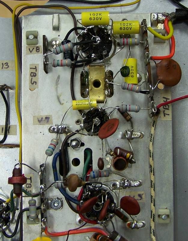 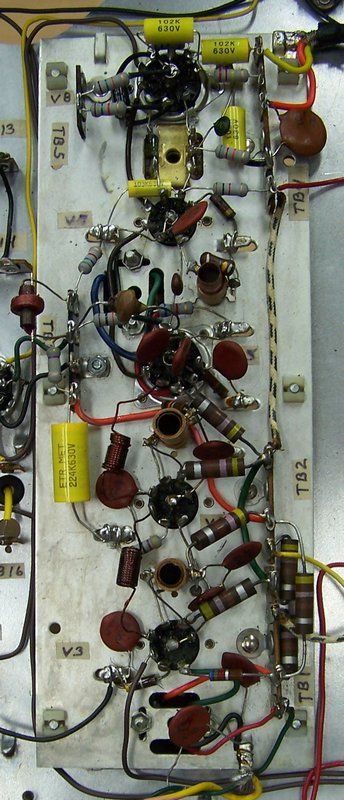
|
|
#98
|
|||
|
|||
|
I like your soldering job a lot better than the ones that built the IF strip.
It looks like they used 50/50 solder. BTW, the new terminal strip you used are getting hard to get, as time goes by. |
|
#99
|
||||
|
||||
|
Nice work!
The soldering on the pre-assembled portions of kits is often pretty lousy, IME. The Heathkit color set that I put together this year had several melted wires, dropped solder blobs, a broken terminal strip, and an unsoldered connection in the high voltage module. I also have a Heathkit frequency counter in my shop that was factory assembled (SM-2420). I got it really cheap because it wasn't working due to several cold solder joints.... |
|
#100
|
||||
|
||||
|
The terminal strips are merely getting hidden away. Mouser has them,
just go to Keystone Electronics under manufacturers, then terminals. Then restrict to lug terminals and go beyond the first page. |
| Audiokarma |
|
#101
|
|||
|
|||
|
Thanks guys for the nice comments.
|
|
#102
|
|||
|
|||
|
I just finished Step 2 (Audio and Video Output) of 6.
I did a minor mod when mounting the audio output transformer. It looks like they provide holes for the transformer but the chassis hole the primary wires go through would be off center and the wires would have to do a quick 90 degree turn then about 1/2 do another 90 degree turn down through the hole. That ain't happening on my watch! What I did was put the wires through the hole straight down and mark the chassis for another mounting hole. I drilled for a 8-32 screw and used some NOS 8-32 hex head screws, washers, lock washers and nuts. Much better and it looks right. 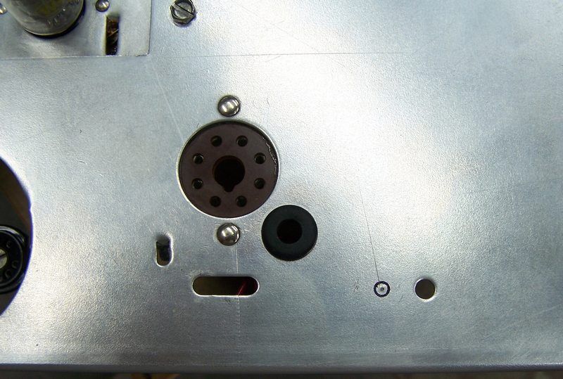 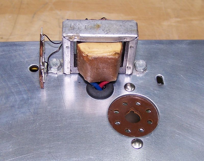 Then in one of the steps they want you to wire the speaker via 12" wires to the terminal strip. Too much left to do to finish this thing to have a speaker hanging by some wires. I did think that a disconnect pug would work great especially when I mount the thing in a cabinet. Here's my question. Does anybody know where I can get a period correct disconnect? We're talking mid 50's here. Last edited by Crist Rigott; 12-17-2016 at 09:28 AM. |
|
#103
|
|||
|
|||
|
I followed the instruction sheet pretty much step-by-step. When I ran a wire or installed a component, I highlighted it on a copy of the instruction sheet. I didn't have the .0047uf film cap yet so I just skipped that step. Also I removed the twin lead from the tuner and chassis because it was in the way and getting beat up from handling the chassis. I removed it a while ago.
I do have question and that is there are 2 peaking coils that I installed. A black dot and a red dot. When I installed them to the terminal strips and tube socket, I installed them a little higher up than I normally would think. I remember always seeing these coils mounted higher than the other components. So I did the same. They are about 1/2" higher than the top on the terminal on the terminal strip. Any comments? 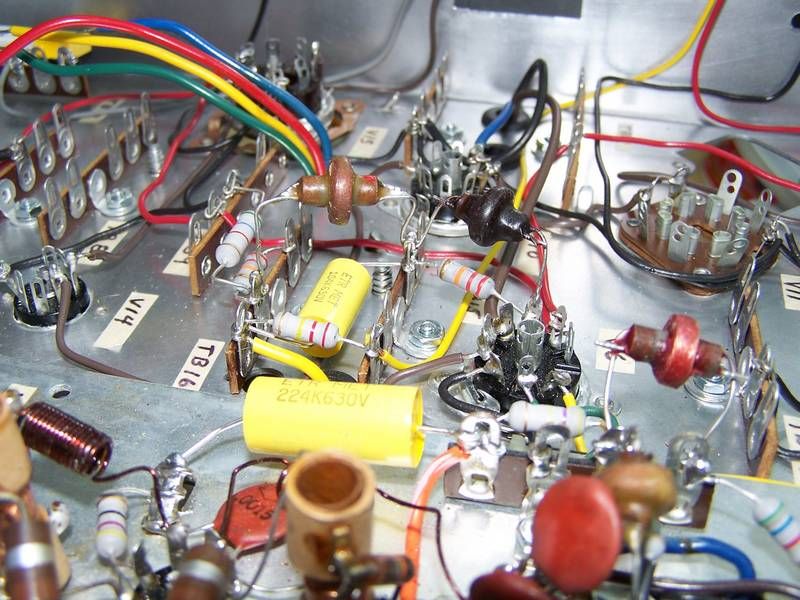 C52, C57, and C62 were all safety caps, rather than the paper caps called out in the instruction sheet. Here are some general photos of where I am. 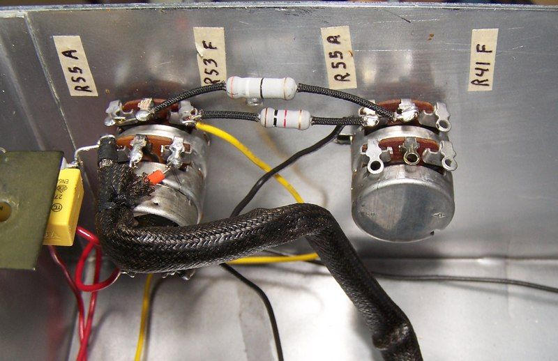 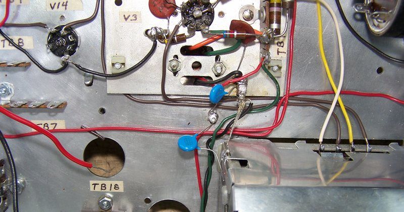 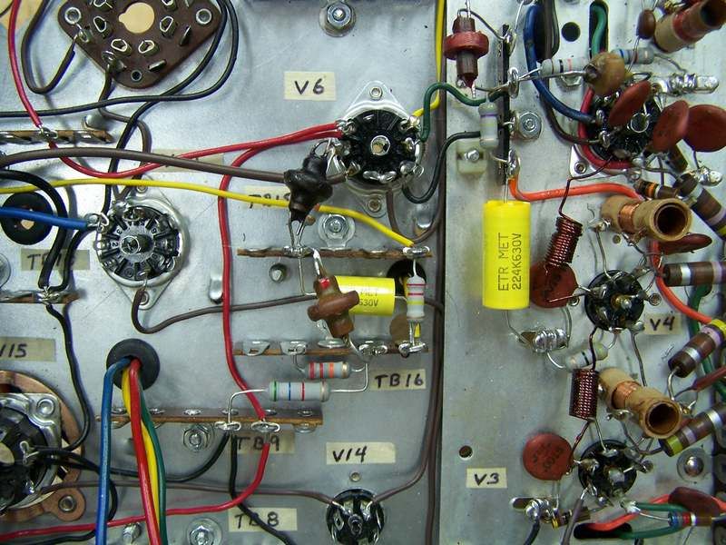 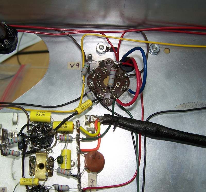 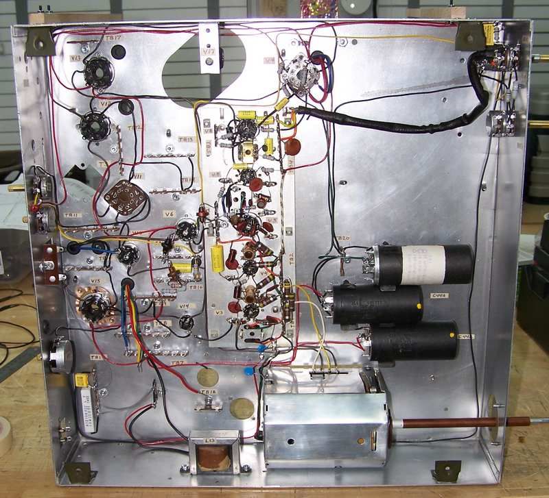
|
|
#104
|
|||
|
|||
|
Here is something I ran across that I could use some comments on.
The schematic on V6 the 12BY7A tube, a wire shown connected to pin 9 and then a comma and then 3. I think this wire (B-) goes to both pins 9 and 3. At least according to the schematic. On the instruction sheet 2 there is no mention to run the jumper from pin 9 to pin 3 nor does the pictorial on the same sheet shows it. I'm guessing that the instruction sheet missed that little jumper. Or did they? Is it needed? I looked at an Emerson schematic which closely resembles this TV and sure enough, the wire goes to both pins 9 and 3. Should I put in that jumper? 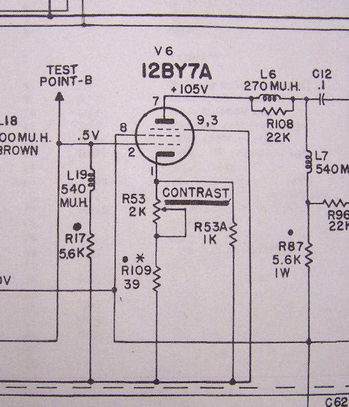 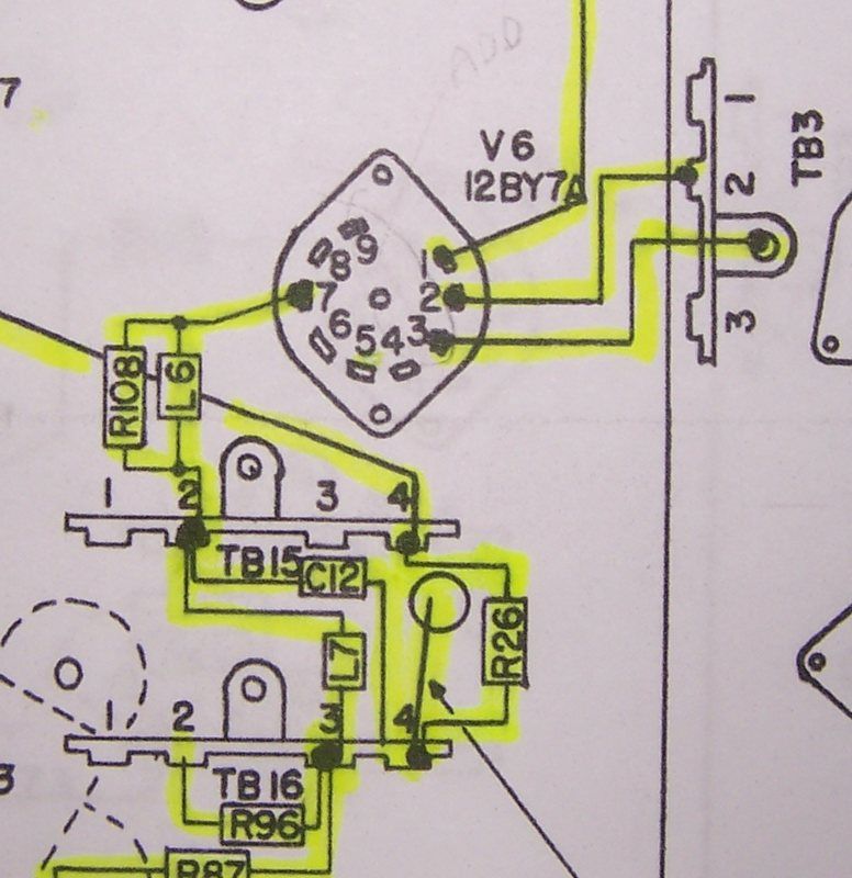
|
|
#105
|
|||
|
|||
|
I just found out that pins 3 and 9 are jumpered in the tube. Nothing else goes to pin 9 so no jumper is needed to be added.
The instruction sheet and the schematic were both correct. |
| Audiokarma |
 |
|
|