Videokarma.org

Go Back   Videokarma.org TV - Video - Vintage Television & Radio Forums > Early Color Television

We appreciate your help

in keeping this site going.
 
 
Thread Tools Display Modes
Prev Previous Post   Next Post Next
  #11  
Old 12-31-2018, 10:34 AM
Electronic M's Avatar
Electronic M Electronic M is offline
M is for Memory
 
Join Date: Jan 2011
Location: Pewaukee/Delafield Wi
Posts: 14,787
Quote:
Originally Posted by etype2 View Post
Update from Mike, December 30, 2018. Day 152

Greetings Marshall. We are finished with the bottom of the chassis, at least FOR NOW. Picture #1 is the top of the chassis again, and it shows nice clean capacitor cans that have been replaced. The rest of it still needs a lot of cleaning and yet, some more components replaced. For now, it is time to rebuild the tuner since the lubricants have long ago turned to something more like plastic rather than grease or oil. But first, I have snapped a picture of the “HUE” control that you speak of and have asked it to be moved to the front of the chassis. This is not going to happen. The HUE control is NOT a POT. It is a coil. There is a flexible cable that is manufactured to fit the top of the slug of the coil and that is their method of changing the phase relationship of the colors. I do not see a “good” way to move this control. It would be problematic since the controls on the front panel are all below the “plane” of the chassis. Anyway, Picture #1 shows this issue. Picture #2 shows the chassis with the nice new electrolytic cans and a “somewhat” dirty chassis. This will be cleaned up a bit during the next restoration phases.

Picture #3 is before the tuner removal.
Picture #4 is the tuner removed.
Picture #5 is the cover removed and you can now see the corroded condition of the contacts on the channel elements.
Picture #6 Channel strips removed.

Picture #7 Inside tuner main shaft removed.

Picture #8 Tuner contacts and body cleaned. And all resistance values checked.
Picture #9 Main shaft and Fine Tuning shaft before cleaning.
Picture #10 Fine tuning shaft, contact spring and detent wheel before cleaning.
Picture #11 Parts ready for re-assembly.
Picture #12 Drum and detent installed.
Picture #13. All strips re-installed, the cover is on and the tuner is ready to re-install.

Tap on images to enlarge. See this link to view 13 images full size. https://visions4netjournal.com/westinghouse/


I think there is a doable reasonable method of achieving front tint control on that model. Drill a hole on the side of the large main chassis, unbolt the tint knob shaft and linkage on the back of the sub chassis, fish the knob shaft end of the flexible linkage through the hole you just made, build an angle bracket to hold the end of the linkage at some practical point under the main chassis with the shaft pointing towards the pencil box controls area, then run a shaft extension from the pencil box area all the way back to that bracket you made somewhere mid under chassis. The flex shaft looks a bit short so where you put the hole and bracket will probably need carefull planning...you may also need to put a universal flex joint (just like on some of the original under chassis shaft extensions) between the the extension shaft and the shaft on the original flex shaft if the mounting arrangement causes them to meet at an angle.


I recently had reason to do a power relay mod similar to yours (and found a better way to do it) on an audio console I was souping up. I don't like those exposed above chassis relay treminals, and found a nice way of eliminating them in my work....They still make relays with octal bases on them for industrial automation (I think they use a different name than octal). I took the back shell from an eye tube socket from a scrapped radio console and an octal socket that the shell fits and put my connections inside the shell with the relay unplugged it looks like an eye tube socket and with the relay connected it still looks much more like a stock part of the set. For those curious: the console had a switched outlet that was getting extra load in the course of fixing the tuner chassis I had to change the power control pot and beefed up it's switch. However the original design did not allow the record changer to control the power of the chassis...I wanted the phono's power switch to have logical OR behavior with the chassis power switch without forcing the phono to spin if the radio was on and the easiest way (a safest for the phono switch) to implement it was a 115V relay coil in parallel with the phono motor with it's contacts inparallel with the chassis power switch.
Photo graphic summary: this is safer and better looking
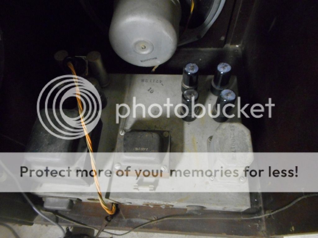


Than this:
[/QUOTE]
__________________
Tom C.

Zenith: The quality stays in EVEN after the name falls off!
What I want. --> http://www.videokarma.org/showpost.p...62&postcount=4

Last edited by Electronic M; 12-31-2018 at 10:39 AM.
Reply With Quote


Thread Tools
Display Modes

Posting Rules
You may not post new threads
You may not post replies
You may not post attachments
You may not edit your posts

BB code is On
Smilies are On
[IMG] code is On
HTML code is Off

Forum Jump


All times are GMT -5. The time now is 08:07 PM.


Powered by vBulletin® Version 3.8.4
Copyright ©2000 - 2024, Jelsoft Enterprises Ltd.
©Copyright 2012 VideoKarma.org, All rights reserved.