Videokarma.org

Go Back   Videokarma.org TV - Video - Vintage Television & Radio Forums > Television Broadcast Gear

We appreciate your help

in keeping this site going.
Reply
 
Thread Tools Display Modes
  #1  
Old 07-18-2011, 03:35 AM
W.B. W.B. is offline
VideoKarma Member
 
Join Date: Nov 2008
Posts: 134
Query on Test Pattern Generator

This has to do with a generator that provided color bars shaped as on the following YouTube clips:
- the end of this 1984 sign-off from CHCH Channel 11 in Hamilton, ON (from point 2:42 onwards)
- the end of this 1985 sign-off from KOLO Channel 8 in Reno, NV (from point 2:36 onwards) - also on this 1986 clip from point 4:33 onwards
- the end of this 1979 sign-off from TV Ontario (from point 3:57 onwards)
- this screen capture from WTVS Channel 56 in Detroit, circa 1980's
All I know is that the tones used were either 400 Hz or 440 Hz; that on the CHCH and KOLO clips, there was added a PLUGE to the EIA RS-189A bars in apparent response to the newer SMPTE ECR 1-1978 (later EG 1-1990) bars; and that it was in use on quite a few other stations in both the U.S. and Canada along the way. Would anyone who frequents this board have any specifics on the make and manufacturer of the generators that provided this kind of horizontal timing (with each bar on the top end about 98 horizontal pixels in a 13.5 MHz clock, or in microseconds, 7.26)? I know it wouldn't have been from Tektronix, whose color bar timing was quite different. Any help on this question would be appreciated.
Reply With Quote
  #2  
Old 07-18-2011, 03:36 PM
ctc17 ctc17 is offline
VideoKarma Member
 
Join Date: Jul 2009
Posts: 1,615
That looks exactly like the Leader generator I use to setup old sets. Not sure on the timing thing.
Reply With Quote
  #3  
Old 07-18-2011, 10:31 PM
bandersen's Avatar
bandersen bandersen is offline
RCA 741PCS
 
Join Date: Mar 2009
Location: Chicago, IL
Posts: 8,098
Ditto. My Leader LCG-400 produces these bars.

__________________
Here are my Vintage Radio & TV YouTube Channel and Photo Gallery

Last edited by bandersen; 07-20-2011 at 12:44 PM.
Reply With Quote
  #4  
Old 07-18-2011, 11:45 PM
ctc17 ctc17 is offline
VideoKarma Member
 
Join Date: Jul 2009
Posts: 1,615
Quote:
Originally Posted by bandersen View Post
Ditto. My Leader LCG-400 produces these bars.
I remember watching your video shortly after I got mine hoping i wouldn't have to change all those teardrops in mine. So far so good. I have seen several pieces of equipment where the tantalums start shorting and they all seem to die about the same time.
Reply With Quote
  #5  
Old 07-19-2011, 07:08 AM
W.B. W.B. is offline
VideoKarma Member
 
Join Date: Nov 2008
Posts: 134
Did TV stations and some post-production houses actually have Leader LCG-400's in their setup? I have seen some late 1960's and early '70's Broadcast Engineering ads with a few whose shapes were ubiquitous:
- Riker Industries Inc. Model 5618 Encoded Color Bar Generator - used into the early 1980's by WXYZ-TV (Channel 7) in Detroit before they switched to the SMPTE color bars (if one saw some of the clips from some of Ray Glasser's various 'videoholic' accounts on YouTube, namely this one)
- Richmond Hill Laboratories TS-13C Color Bar Generator
Reply With Quote
Audiokarma
  #6  
Old 07-19-2011, 01:41 PM
bandersen's Avatar
bandersen bandersen is offline
RCA 741PCS
 
Join Date: Mar 2009
Location: Chicago, IL
Posts: 8,098
It wouldn't surprise me. The LCG-400 is rack mounted and had output connections on the back suitable for professional equipment.
__________________
Here are my Vintage Radio & TV YouTube Channel and Photo Gallery
Reply With Quote
  #7  
Old 07-19-2011, 08:26 PM
3Guncolor 3Guncolor is offline
VideoKarma Member
 
Join Date: Mar 2005
Posts: 312
Yes they were used at broadcast stations. We had one as a backup it can even "gen lock".
Reply With Quote
  #8  
Old 07-20-2011, 06:49 AM
W.B. W.B. is offline
VideoKarma Member
 
Join Date: Nov 2008
Posts: 134
Seeing that shot taken of the TV screen showing the EIA bars, it doesn't look like that would be from the same generator that yielded the bars as referred to in those clips and WTVS screencap.
Reply With Quote
  #9  
Old 07-20-2011, 12:46 PM
bandersen's Avatar
bandersen bandersen is offline
RCA 741PCS
 
Join Date: Mar 2009
Location: Chicago, IL
Posts: 8,098
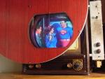
They pretty much look the same to me. What differences are you referring to ? My camera is out of sync with the TV. That's why the top half is darker.
I think the square at the bottom that looks more purple in the WTVS screencap might be due to the TVs color settings.

__________________
Here are my Vintage Radio & TV YouTube Channel and Photo Gallery
Reply With Quote
  #10  
Old 07-20-2011, 05:24 PM
W.B. W.B. is offline
VideoKarma Member
 
Join Date: Nov 2008
Posts: 134
The bars on the screencap lean towards the left. In a 13.5 MHz clock setting, I measured each of the seven bars at 98 horizontal pixels, x 7 = 686, and there's about 20 or 25 horizontal pixels of black on the right. If the Leader generator you have was the same as used by WTVS, the bars on your screen would've leaned slightly left, and you'd see less white on the left side than blue on the right. On your screen the bars from left to right are centered.
Reply With Quote
Audiokarma
  #11  
Old 07-20-2011, 07:04 PM
Electronic M's Avatar
Electronic M Electronic M is offline
M is for Memory
 
Join Date: Jan 2011
Location: Pewaukee/Delafield Wi
Posts: 14,787
This could be a case of being confused by uncentered CRTs that are being over scaned.

Tom C.
Reply With Quote
  #12  
Old 07-21-2011, 05:51 AM
W.B. W.B. is offline
VideoKarma Member
 
Join Date: Nov 2008
Posts: 134
Quote:
Originally Posted by Electronic M View Post
This could be a case of being confused by uncentered CRTs that are being over scaned.
No, I've studied different timings of color bars. I even have timing info on the SMPTE color bars from Tektronix TSG-170A generators, thanks to manuals I've seen online (the middle five bars, in 13.5 MHz clock timing, are 101 horizontal pixels in width while the two on each side are 103; the sum total is 711 which is the horizontal picture width by this count, and which corresponds to the 52.66 µs figure commonly cited in old analogue NTSC measurements).

No, the EIA bars I've asked about are indeed uncentered. And seemingly by some kind of design.
Reply With Quote
  #13  
Old 07-24-2011, 08:45 PM
Penthode's Avatar
Penthode Penthode is offline
VideoKarma Member
 
Join Date: Jun 2009
Location: Kitchener/Waterloo Ontario Canada
Posts: 1,059
The generators would have likely been the station sync generator which may have doubled as the test signal generator. Most likely a Tektronix device in those days.

I am not sure why we are discussing the reference to a 13.5MHz clock. The mid eighties was before ITU R 601 sampling. The clock reference in the generators would have been 4fsc or 4X 3.58 = 14.3 MHz.

Terry
Reply With Quote
  #14  
Old 07-25-2011, 07:29 AM
W.B. W.B. is offline
VideoKarma Member
 
Join Date: Nov 2008
Posts: 134
Quote:
Originally Posted by Penthode View Post
I am not sure why we are discussing the reference to a 13.5MHz clock. The mid eighties was before ITU R 601 sampling. The clock reference in the generators would have been 4fsc or 4X 3.58 = 14.3 MHz.
Or more specifically, 14.31818182 . . . MHz. In this case, the bars in question would have been 104 in width (except the first which in some applications stood at 106). However, with very few exceptions, the screencaps that are out there are not even done in this sample rate. Nor in the 17.734475 MHz (4 x 4.43361875) that was the composite sample rate for PAL standard. But with picture width at 754 pixels in the 14.31818182 . . . MHz sample clock, the horizontal timing of the top of the bars in this layout as on that WTVS screencap (and on those YouTube clips) would have been:
106 + 104 + 104 + 104 + 104 + 104 + 104 + 24 (black)
The lower portion would have been, with PLUGE added:
130 + 132 + 130 + 52 + 52 + 78 + 52 + 128
The vertical timing, unless I'm mistaken, would've been 21-200 and 263-442 for the top part, and 201-263 and 443-525 for the bottom.
Reply With Quote
  #15  
Old 08-27-2011, 01:38 AM
cbenham's Avatar
cbenham cbenham is offline
VideoKarma Member
 
Join Date: May 2006
Posts: 471
Quote:
Originally Posted by W.B. View Post
Or more specifically, 14.31818182 . . . MHz. In this case, the bars in question would have been 104 in width (except the first which in some applications stood at 106). However, with very few exceptions, the screencaps that are out there are not even done in this sample rate. Nor in the 17.734475 MHz (4 x 4.43361875) that was the composite sample rate for PAL standard. But with picture width at 754 pixels in the 14.31818182 . . . MHz sample clock, the horizontal timing of the top of the bars in this layout as on that WTVS screencap (and on those YouTube clips) would have been:
106 + 104 + 104 + 104 + 104 + 104 + 104 + 24 (black)
The lower portion would have been, with PLUGE added:
130 + 132 + 130 + 52 + 52 + 78 + 52 + 128
The vertical timing, unless I'm mistaken, would've been 21-200 and 263-442 for the top part, and 201-263 and 443-525 for the bottom.
The pics in this thread look like standard SMPTE BARS to me. Of course I may be missing your point entirely on the timing issue. The Tek TSG-100 portable test pattern generator includes SMPTE BARS and 1KHz tone, although I'm sure the oscillator frequency could be lowered. Hope this helps.
Cliff
Reply With Quote
Audiokarma
Reply


Thread Tools
Display Modes

Posting Rules
You may not post new threads
You may not post replies
You may not post attachments
You may not edit your posts

BB code is On
Smilies are On
[IMG] code is On
HTML code is Off

Forum Jump


All times are GMT -5. The time now is 09:33 PM.


Powered by vBulletin® Version 3.8.4
Copyright ©2000 - 2024, Jelsoft Enterprises Ltd.
©Copyright 2012 VideoKarma.org, All rights reserved.