
|
|
|
#106
 06-22-2018, 12:15 AM
|
|||
|
|||
|
Quote:
(If the 5300 were 5000, the figures would be exact.) 
|
|
#107
06-22-2018, 08:01 AM
|
|||
|
|||
|
[QUOTE=
The parts list describes R209 as: "Wire wound resistor, 5300 ohms, 20 watt; 500 ohms, 2 watt; and 500 ohms, 2 watt." Not sure what to make of that description. Why only 2 watts for the 500-ohm segments? [/QUOTE] Power in each segment uses the formula P=(I^2)R. Since the resistor section are in series, the same current would go through all resistor sections. The 500 ohm sections are approximately 1/10 the value of the 5300 ohm section; hence, their power handling capacity would need to be only 1/10 the wattage of the 5300 ohm section.
|
|
#108
06-22-2018, 11:01 AM
|
||||
|
||||
|
I think it means the first section is 5300, in series with a 500 and another 500, so total is 6300. Power is I squared times R, so if the current is approximately the same magnitude for all settings, the smaller resistors in the series string need proportionally smaller wattage. So, one tenth the R --> one tenth the watts.
|
|
#109
06-22-2018, 12:57 PM
|
||||
|
||||
|
Ah, another forehead-slap moment. Lower resistance means lower wattage, duh.
I reviewed the photos that I took while experimenting, and it's clear that increasing the resistance stretches the left half of the image, while decreasing resistance squeezes the left half. Changing the resistance also changes the overall width somewhat. And it does not really cure the non-linearity I'm seeing. The far left edge is still squeezed, etc. And there is an additional variable -- the value of the .22 cap added to increase the overall width. Finding the best setting looks like a very iterative process: -- Try new resistor value -- Adjust the width, horizontal linearity, and horizontal drive controls for best linearity -- Try another resistor value -- Adjust all the etc. -- Repeat, repeat (maybe also adjusting the value of the .22 width-coil cap to see how that effects everything) That would be simpler with a direct-view TV, which you could plop onto the workbench and easily view while adjusting. Not so much fun when you are crouching on the floor to make adjustments and peering around to view the results in a little serviceman's mirror on the other side of the cabinet. OK, enough whining already! I hope to make some progress this weekend. Phil Nelson Quote:
Last edited by Phil Nelson; 06-22-2018 at 03:38 PM.
|
|
#110
06-22-2018, 03:35 PM
|
||||
|
||||
|
Quote:
*My college only stocked 1/2W resistors so when the maths for a circuit design called for a 10W+ resistor that needed to last 30min of various measurements and tests without burning up we had to get creative with series-parallel combos to get a safe wattage...And the professors and parts room folks always wondered why there were so many off tolerance resistors in stock.  What kind of connectors does the main chassis use to hook into the cabinet projection system?... If it is just a set of octal and or Fat-pin tube base/socket connectors (and maybe a CRT socket/HV lead) why not make 5'-12' extender cables so you can keep the cabinet next to the bench and have the chassis on the bench connected to the cabinet for easy adjustment and testing....I did just that when I was working on my 21CT55 to make things easier for me.
__________________
Tom C. Zenith: The quality stays in EVEN after the name falls off! What I want. --> http://www.videokarma.org/showpost.p...62&postcount=4 Last edited by Electronic M; 06-22-2018 at 03:43 PM.
|
| Audiokarma |
|
#111
06-22-2018, 11:15 PM
|
||||
|
||||
|
Extender cables would be handy, although not super-easy.
Two of the three cables would be do-able. The yoke connector is 9-pin, roughly the size of an octal socket with a ninth pin near the center. A second cable goes to the HV power chassis with a 4-pin connector. I don't have such connectors on hand, but I suppose you could scrounge them somewhere. The CRT cable looks tricky. It uses a funky 5-pin connector of a type I haven't seen before. The cup has terminals on the inside and it slides over the butt end of the CRT, which has little metal tabs around its edge.  Weird,wild stuff, as Johnny Carson used to say. You wouldn't need an extender for the HV cable to the CRT second anode, since that doesn't come from the main chassis. It only goes between the two boxes of the Protelgram unit (HV power chassis and optical box holding the CRT). Phil Nelson Phil's Old Radios https://antiqueradio.org/index.html
|
|
#112
06-22-2018, 11:56 PM
|
||||
|
||||
|
CRT base appears to be a euro tube connector...I once was at a swapmeet where someone had some really old Brittish or German tubes with that style of connector...Some had a different number of 'pins'. I had the same impression when I saw them there for the first time...
In your shoes if I did not much like the set, badly wanted/needed service convenience, or had a situation where the wiring to the interconnects was damaged or otherwise unoriginal I'd be tempted to cut the harnesses and insert some other connector that I could easily make (or use an existent) extender for...In any case it's your set, your back/knees, your call.
__________________
Tom C. Zenith: The quality stays in EVEN after the name falls off! What I want. --> http://www.videokarma.org/showpost.p...62&postcount=4 Last edited by Electronic M; 06-23-2018 at 12:04 AM.
|
|
#113
06-25-2018, 10:01 PM
|
||||
|
||||
|
Quote:
|
|
#115
07-03-2018, 04:19 PM
|
||||
|
||||
|
Thanks, that does look like the tube base. The Phillips 3NP4 data sheet is at:
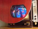
https://frank.pocnet.net/sheets/201/3/3NP4.pdf In an effort to eliminate more variables, I tried injecting video and audio directly at the amplifiers, bypassing the tuner and IF stages. The results were good, so I wired in cables and made a little junction box where I can plug in A/V cables from a DVD player, etc. 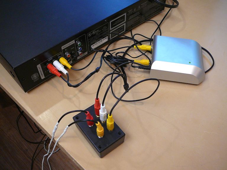 The picture looks better than before, and the audio is outstanding: 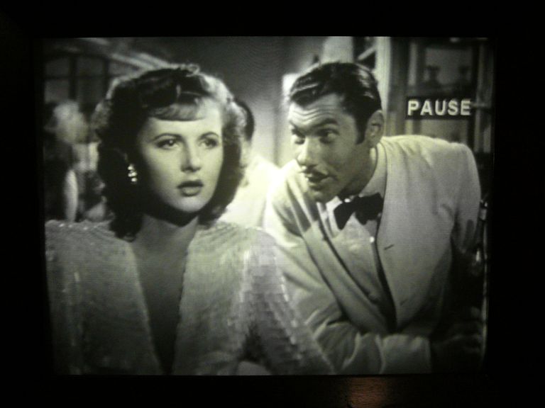 More details in my article at: https://antiqueradio.org/Emerson609P....htm#Injection The screen geometry is approaching normal. The picture is still somewhat off-center horizontally, a condition I hope to cure by raising the optical box using its bottom "tilt" adjusters. Phil Nelson Phil's Old Radios https://antiqueradio.org/index.html
|
| Audiokarma |
|
#116
07-03-2018, 04:42 PM
|
||||
|
||||
|
There is something unusually appropriate about how a B&W movie looks on a period projection...TV.
 
__________________
Tom C. Zenith: The quality stays in EVEN after the name falls off! What I want. --> http://www.videokarma.org/showpost.p...62&postcount=4
|
|
#117
07-03-2018, 08:24 PM
|
||||
|
||||
|
I agree Tom. I think the key word is "projection". What we see is an intensification of the brightness in the center if the screen and less in the outer regions. I would think in both the movie theater and the projection TV you have this effect to some degree due to the use of projection lenses taking a small image and projecting it magnified onto a screen.
In any event I love the way it looks.
__________________
Vacuum tubes are used in Wisconsin to help heat your house. New Web Site under developement ME http://AntiqueTvGuy.com
|
|
#118
08-08-2018, 01:06 AM
|
||||
|
||||
|
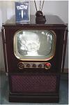
OK, I'm declaring this project finished. The picture is very watchable and I got around to touching up the cabinet:
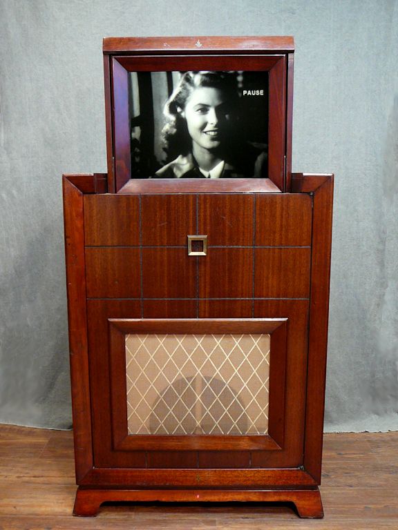 This article provides many details: https://antiqueradio.org/art/Emerson...onFinished.jpg One question in parting: why did Emerson use a pattern of tiny concentric grooves in the face of the display screen? In this extreme close-up, I heightened the contrast to exaggerate the circular pattern, which is imperceptible at a normal viewing distance: 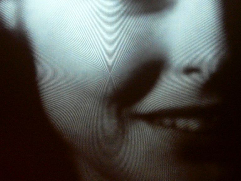 I have a couple of guesses (see article above), but optics is not my strong suit, and I haven't restored any other projection sets, so if you know the answer, kindly clue me in! Regards, Phil Nelson Phil's Old Radios https://antiqueradio.org/index.html Last edited by Phil Nelson; 08-08-2018 at 01:48 AM.
|
|
#120
08-08-2018, 06:30 AM
|
||||
|
||||
|
Awesome! For the first time since I started collecting these sets you've changed my mind about projection TV's. I had no idea the picture could be that nice. Often you see them not restored as well as yours and the picture is rather muddy.
|
| Audiokarma |
 |
|
|


 Linear Mode

