
|
|
|
|
|
#1
 04-25-2014, 02:35 PM
|
||||
|
||||
|
Quote:
 Only downside is the cap now retains a charge for a long time. I suppose I could add a high value bleeder resistor across it. Only downside is the cap now retains a charge for a long time. I suppose I could add a high value bleeder resistor across it.

|
|
#2
04-26-2014, 03:40 PM
|
|||
|
|||
|
Quote:
rrrhre2s
|
|
#3
11-10-2012, 08:22 PM
|
||||
|
||||
|
I decided to give this veneer a try. It's real mahogany sliced very, very thin with a paper backer.
I've got about 10 feet on ebay for 12 bucks so plenty to experiment with. First I'll try a test with red mahogany stain. 
|
|
#4
12-09-2013, 01:55 PM
|
||||
|
||||
|
Thanks, yes, this is the same set. I'll give that a try next time I get it up on the workbench.
|
|
#5
02-06-2014, 10:24 AM
|
||||
|
||||
|
I used two of the 1 Amp max versions in series to best approximate the 400 ohm original.
The steady state resistance of these devices depend on the current through them. Running only 0.6A through the 2A version would result in a fairly high "hot" resistance. Yes, 82pF. I left all the original ceramic caps in place.
|
| Audiokarma |
|
#6
02-20-2014, 08:04 AM
|
||||
|
||||
|
Just about ready to plug in the variac and give my Predicta a first go. The only thing I can't find nor figure out is.....while attaching the picture tube, there are two single long leads.....one of which goes to pin 2 on the picture tube, the other goes to pin 6.
I can't see where the heck they're supposed to plug into the chassis. Anyone know offhand?
__________________
"Restoring a tube TV is like going to war. A color one is like a land war in Asia."
|
|
#7
02-20-2014, 08:46 AM
|
||||
|
||||
|
I believe pin 2 is the video which goes to a post on the main board. Pin 6 is focus which goes to either ground or boost - which ever gives better focus.
Last edited by bandersen; 02-20-2014 at 08:57 AM.
|
|
#8
02-20-2014, 08:52 AM
|
||||
|
||||
|
Any idea of *where* on the board these go? I can't find any info on it anywhere.....and there are a lot of posts on the main board.....
__________________
"Restoring a tube TV is like going to war. A color one is like a land war in Asia."
|
|
#9
02-20-2014, 09:01 AM
|
||||
|
||||
|
The one that doesn't have any wire wrapped around it.
|
|
#10
02-20-2014, 09:37 AM
|
||||
|
||||
|
I believe that I found pin 6's connection to chassis, please confirm that I'm correct here:
http://antiqueradio.org/art/predicta16.jpg Now, just have to figure out where the other wire goes. I swear that I noted this somewhere, but the set's been apart for two months now, and I can't find anything I might have written.
__________________
"Restoring a tube TV is like going to war. A color one is like a land war in Asia."
|
| Audiokarma |
|
#11
02-20-2014, 10:06 AM
|
||||
|
||||
|
I think you have the CRT pin numbering off a little. Pins 2&6 are connected internally to the focus element. Pin 7 is the cathode which connects to the video output.
Page 17 of the Sams Photofact shows how the wires connect to the main board. That's what they call "CircuiTrace Numbers". #20 goes to the cathode of the CRT (pin 7 not 6). That's what you have labelled as "CRT lead" The last wire should end in a spade terminal. There are two possible places for it to connect on a little terminal strip in the center of the chassis. If all else fails, you can just leave it disconnected. The CRT may be a little out of focus but will work.
|
|
#13
04-24-2014, 01:48 PM
|
||||
|
||||
|
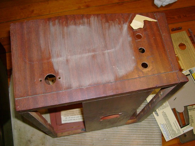
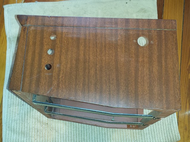
Now that the weather is FINALLY warmer, I started work on the cabinet.
I found the thermistor disc while cleaning out the cabinet. I wonder how many sets were retired because the disc fell out ?  The sides and front are in pretty good shape.  I figure they used a metal mesh bottom for ventilation.  I'll try to touch up all the nicks and dings.  Legs and bottom removed. It may looks like real mahogany, but I'm pretty sure it's poplar painted red.  Fully disassembled cabinet. I made an attempt to touch up the large area of finish loss on top, but it looks terrible.  So off it comes. Much was scrapped off and liquid stripped used in the stubborn areas.  New paper veneer prepared. I coated both surfaces with TiteBond Wood Glue and allow to dry. This particular glue can be reactivated with heat for seven days.  Not bad, but I might give it another try. This veneer is so thin that any defect, including variation in glue thickness, is telegraphed onto the surface. It's so thin that they can;t be sanded out.  Finally, after a little Brown Mahogany Mohawk toner. It's a little darker and redder than the original but not bad. If I were to do it again, I'd try Prefect Brown toner instead. 
|
|
#14
04-24-2014, 01:52 PM
|
||||
|
||||
|
As for the sides, a little light sanding with 400 grit and a fresh coat of lacquer works well. No issues with finish compatibility.
  Switching gears a little to the antenna. All this set had left when I got it was the plastic base. A few months back I came across this great ARF thread on fabricating one using salvaged rabbit ears. Luckily, I have more of mine left and just need a replacement telescoping rod. Eventually, I managed to find one and it's a perfect fit 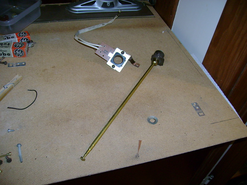 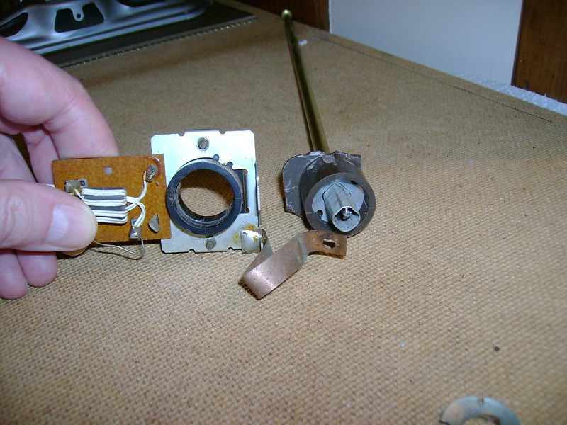 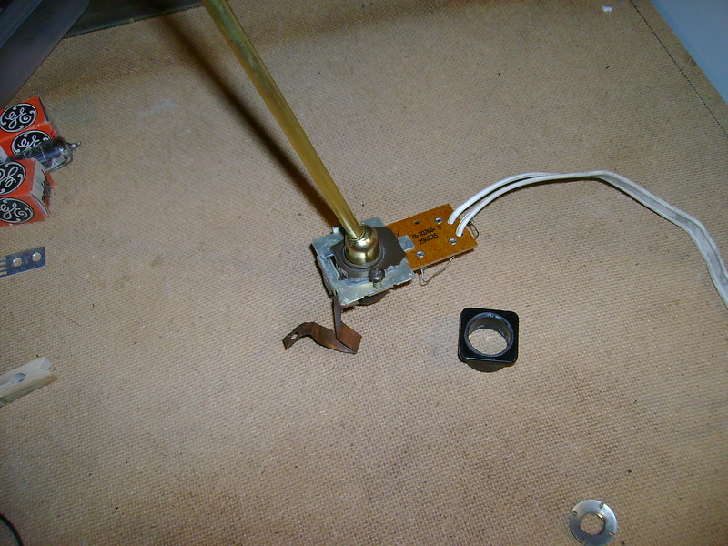 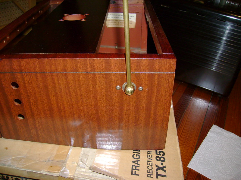
Last edited by bandersen; 04-24-2014 at 02:07 PM.
|
|
#15
04-24-2014, 03:11 PM
|
||||
|
||||
|
Looking mighty fine.

|
| Audiokarma |
 |
|
|


 Hybrid Mode
