
 |
|
|
|
#1
|
|||
|
|||
|
Well, I started messing with the kit. I went up to the copy place and made copies and pdf's of the 6 instruction sheets to assemble the TV, the instruction booklet that goes into alignment and troubleshooting. The booklet also has the schematic which again I made a large copy and then pdf it. Also a large sheet that covers the IF strip instructions was copied and pdf. The pdf's are huge like from over 1mb to just under 5mb. I'll share those with everybody if I knew how. I also have copies and pdf of the Supplementary sheets. Basically if it came with the kit, it was copied and pdf!
Over the years the chassis cad plating has turned a yellowish green both on the top and underneath the chassis and yoke support. I have several pictures that show how bad it was. 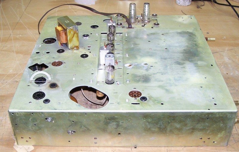 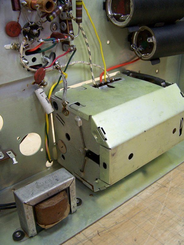 Here is a picture of the IF Strip from the bottom: 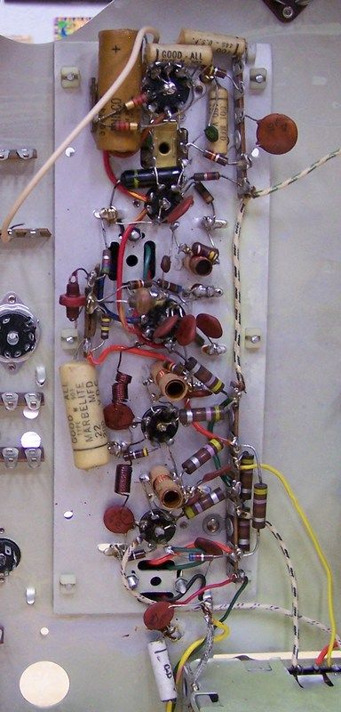 I did inventory and took a lot of pictures of each bag. That will be a separate post. Here is another view of the bottom of the chassis: 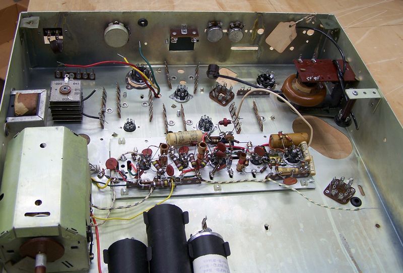 Here is proof that it was aligned: 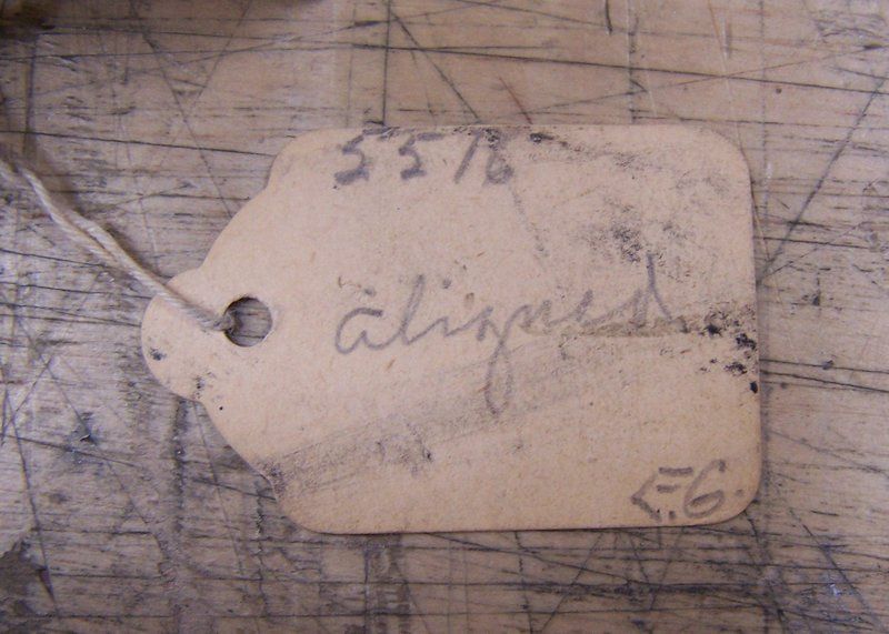
Last edited by Crist Rigott; 12-01-2016 at 10:49 PM. |
|
#2
|
|||
|
|||
|
I cleaned the chassis, yoke support, tuner, etc to get rid of the cad plating. I read somewhere that simple Green works great. It does! What I did was to pull the tuner, IF strip, filter caps, Selenium rectifier, fly back transformer, vertical output transformer, rubber grommets, all the pots, the HV rect. tube socket, etc. If I could unscrew it, it came off. This made the job a lot easier. I first masked off the tube sockets both top and bottom, then I would spray on some cleaner and then rub it around then after a few seconds I used a terry cloth to scrub and wipe the chassis clean. In reality, not much scrubbing. I also would use an acid brush and Q-Tips where needed. Once cleaned I would do the same thing again only with rubbing alcohol to further clean the metal.
Once that was done both top and bottom, I then used some Brasso to "even" out the look of the metal. Only this was done on the top, sides, and both sides of the yoke support. After that I wiped down the metal with WD-40. I then installed new rubber grommets. Here are some pics now that I'm done. Here is the bottom of the chassis with everything installed back in that is going to get installed for now. 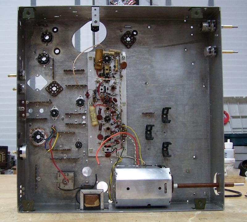 Here are some different views of where I am : 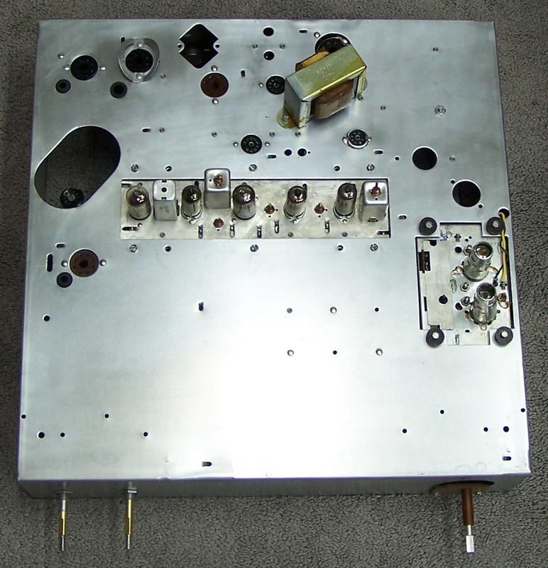 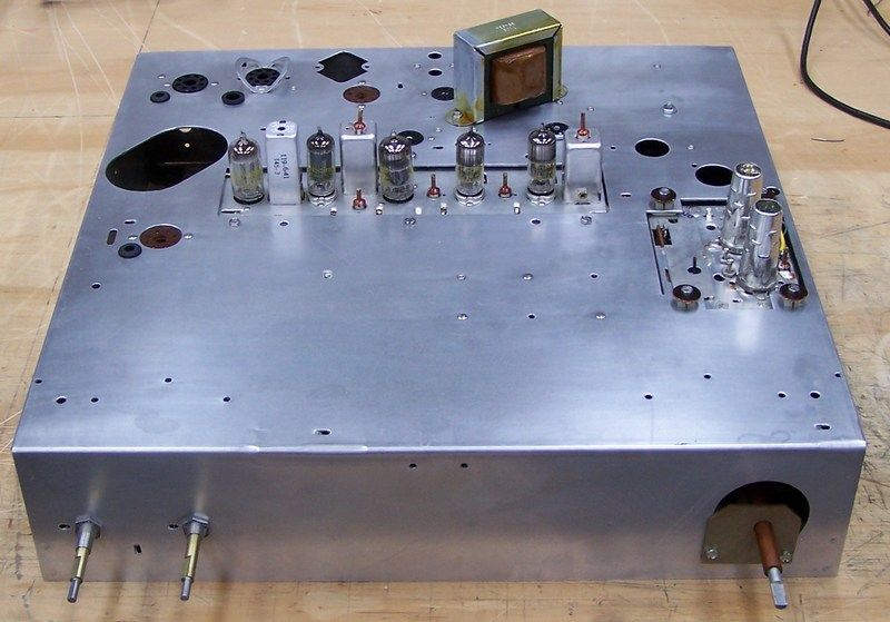 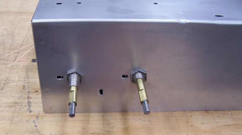 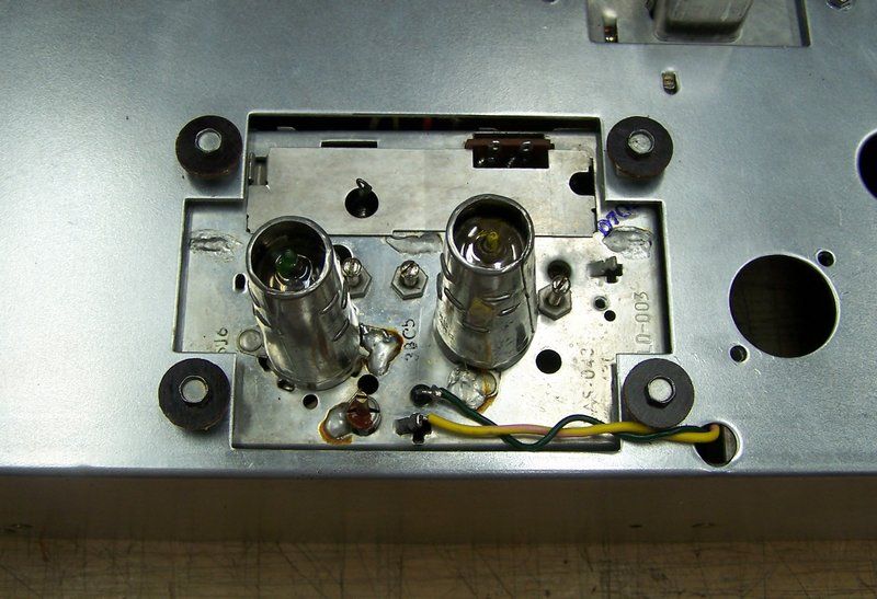 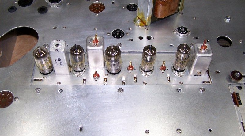 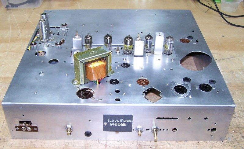 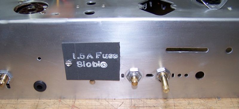 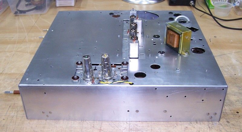
Last edited by Crist Rigott; 12-02-2016 at 10:34 AM. |
|
#3
|
||||
|
||||
|
Nice cleaning job! The transformer was likely dipped in insulating varnish after assembly.
I hope you were careful cleaning that chassis, as that yellow cadmium corrosion is pretty toxic stuff.... |
|
#4
|
|||
|
|||
|
Quote:
Yup, I was careful. |
|
#5
|
||||
|
||||
|
Your HV lead has an inline plug on it....That might fit my CTC-4 HV receptacle. If you want to sell your HV lead or it swap for one off a 90's CRT TV just PM me.
__________________
Tom C. Zenith: The quality stays in EVEN after the name falls off! What I want. --> http://www.videokarma.org/showpost.p...62&postcount=4 |
| Audiokarma |
|
#6
|
|||
|
|||
|
That just might happen. I'll keep you in mind when the time comes. Thanks for the offer.
|
|
#7
|
|||
|
|||
|
OK guys, I have a bit of a problem that needs to be worked out. Basically it is the wires that I add to the chassis are called out in the step by step as far as length and to/from. But the step by step never gives the color of the wire to be used.
I have 9 different colors that the kit included. See Wire Bag above. I have the most wire in red and black. The the other colors are about 10 to 20% of what the red and black wires are. I have 1 wire that's about 18 inches long and the color of it is white with an orange stripe. I created a "wire schedule" in Excel listing all the wires in each of the 6 instruction sheets. I'm guessing that the color wire to be used depends on either the circuit or function. For example in the Admiral I just finished, orange went to a filter cap and was like B+ IIRC, etc. Is there a chart that would show what colors should be used depending on the circuit/function? I know that black is usually ground but in this case it could be B- because B- floats off of the chassis. Red could be B+ of 130 volts. I'm including some attachments that might help explain my situation. They are a schematic, a "snapshot" of the step by step instructions from sheet 1, and my wire schedule. I figured that I could sort the wires by circuit/function to help get what I need for colors. |
|
#8
|
||||
|
||||
|
Radio Daze provides this handy color code chart. Of course this stuff in old text books as well.
http://www.radiodaze.com/vintage-component-color-code/ |
|
#9
|
|||
|
|||
|
Quote:
I did start to trace out the wiring and as far as step 1 goes, it looks like it is wiring B-, B+ etc. So I'm starting to fill in my chart. I'll use that chart as a guide and see how that works out especially with the wire lengths provided. |
|
#10
|
||||
|
||||
|
They probably selected "controlled warm up" tubes (octals often had a 'GTA' or 'GTB' post fix to identify that IIRC) for the design...Controlled warm up tubes would warm up in sync IIRC by sensing heater current so no tube would be momentarily taking a bigger portion of the voltage than designed.
A thermistor or dropping resistor would not hurt, but is not essential either IMO.
__________________
Tom C. Zenith: The quality stays in EVEN after the name falls off! What I want. --> http://www.videokarma.org/showpost.p...62&postcount=4 |
| Audiokarma |
|
#11
|
|||
|
|||
|
Quote:
|
|
#12
|
|||
|
|||
|
I have decided to wire the TV like the kits shows. I will use safety caps where needed and I replaced the Selenium rectifier with a 2 lug terminal strip and a 1N4007 diode. On the schematic, there looks like 300ma by the selenium rectifier. I'm guessing that either this is the rating of the rectifier or the total current draw through the rectifier. In any case a 1 amp diode exceeds those numbers by a factor of 3.
I started step 1 (Power Supply and Filament) yesterday (Monday) and finished it today (Tuesday). Some observations are in order. All-in-all the step by step instructions and the pictorial work very well and the steps are in a logical order. For instance, to wire the filament string, you start at the fuse holder then wire the first tube as in the schematic (V15), then the next wire goes to V14 and so down the filament string. Working with 20awg solid hook-up wire can be a bit trying especially on the small 7 pin tube sockets. Those terminals are fragile! No mishaps yet. The wire lengths given is the step-by-step are for the most part fairly accurate. There were about 6 wires where I changed the length by maybe an inch. One wire was 2 inches too long. So far this was the only big error in wire lengths. I'd rather have it long than too short. Of course I trimmed the wire to a more reasonable length. I routed the wires per the instruction sheet all within reason. For R69 a 5 Ohm 5W resistor just at the minus side of the rectifier I used a 22 Ohm 10W sand resistor simply because that's what I had. Once the TV is up and running and with the 122Vac line voltage applied, then the resistor will be substituted for the correct value and wattage. Most likely be a gold chassis mount type resistor. You can see this resistor in the lower left corner of the chassis along with C54, the Safety cap. Oh, yeah, I labeled each terminal strip, tube, and pot with small pieces of masking tape to help to ID the component location. 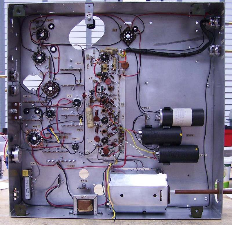
Last edited by Crist Rigott; 12-17-2016 at 09:27 AM. |
|
#13
|
|||
|
|||
|
Quote:
It's a rather large undertaking for a person without the restoration, kit building and troubleshooting skills that many of us have on this forum. 
|
|
#14
|
|||
|
|||
|
Well with the talent and help of this forum, I'm sure I'll be successful.
|
|
#15
|
|||
|
|||
|
I like your soldering job a lot better than the ones that built the IF strip.
It looks like they used 50/50 solder. BTW, the new terminal strip you used are getting hard to get, as time goes by. |
| Audiokarma |
 |
|
|