
|
|
|
|
|
#1
 02-18-2016, 09:29 PM
|
|||
|
|||
|
Wow .I remember the days of the late night test patterns.Thanks Telecruiser for the info on the video playback device .I've been looking for something like that for years.

|
|
#2
11-17-2021, 07:16 PM
|
|||
|
|||
|
Quote:
 And the other zigzag wedge dated at the earliest to 1965: 
|
|
#3
12-27-2011, 11:16 PM
|
||||
|
||||
|
The old round test patterns (Indian head and ones used by local stations) aren't needed much anymore with sets from about the 1980s to now (especially the latter), which is probably why TV stations, the few that that still sign off at one or 2 a.m., anyway, use the color bar test chart, with their call signs, channel numbers and city of license in the black area below the bars, but ahead of the large white square at the extreme right edge of the chart. The round pattern is useful when adjusting image proportions (height, linearity, width) on old sets that have variable controls for such, while the color charts can be put to good use when adjusting the 3.58-MHz color burst phase (or to diagnose color registration problems) on vintage color sets.
Some local TV stations put their call signs and channel number on the Indian head pattern as well. Many years before American and Canadian television went digital (also before I had cable), I remember seeing a pattern from CFPL-TV in London, Ontario with just that information at the top of the pattern. I could also get Windsor's CKLW-TV (now CBET) channel 9 when the conditions were right, but I don't remember ever seeing their location and channel info on their test pattern. At least one Cleveland TV station (NBC affiliate WKYC on channel 3) used a round test pattern with color segments built right into the pattern. Never saw anything like it; in fact, I think that station was the only Cleveland TV station to use such a unique test pattern. Channel 5 had a standard round pattern, as did channel 8, although 8's pattern also, IIRC, had color segments incorporated into it. Cleveland's PBS channel 25, which first signed on in 1965, had a round b&w pattern, no color bars or segments; however, when Cleveland's first commercial UHF station went on the air in 1968, it used a squarish test pattern with one small color bar chart at the top, IIRC. The station's call letters were placed below that chart, with one letter of the call sign appearing directly over the vertical resolution test wedge. Channel 19's test signal was simply a color chart, with the station's call sign and location info at the base of the chart -- again, very near the white square at the right edge. An independent station on channel 55 (now an affiliate of The CW) that went on the air in 1985 in the Cleveland area, but was licensed to and was intended to serve an area 30 miles southwest of the city, also used a color chart; somewhere, I have a VHS video tape on which I recorded the station's test signal after the end of a program. The station is WBNX-TV, CW55, Akron-Cleveland, Ohio. To the best of my knowledge and belief, however, they never used a round test pattern; neither, for that matter, did Cleveland's original channel 61, Kaiser Broadcasting WKBF-TV (now WQHS-TV Univision 61). Maybe by this time (late '60s), traditional test patterns had gone out of style? 
__________________
Jeff, WB8NHV Collecting, restoring and enjoying vintage Zenith radios since 2002 Zenith. Gone, but not forgotten. Last edited by Jeffhs; 12-27-2011 at 11:21 PM.
|
|
#4
12-28-2011, 03:42 AM
|
|||
|
|||
|
Quote:
- WIBF (Channel 29, later WTAF and now WTXF), Philadelphia, PA - WCMC (Channel 40, now WMGM), Wildwood, NJ - WNDT (Channel 13, now WNET), Newark, NJ/New York City* - WNJU (Channel 47), Linden/Newark, NJ* - WFLD (Channel 32), Chicago - WXTV (Channel 41), Paterson, NJ* - WQLN (Channel 54), Erie, PA - WMAA (Channel 29), Jackson, MS - KAID (Channel 4), Boise, ID) - KGMB (Channel 9), Honolulu, HI - WLS (Channel 7), Chicago (the famed "Sears Tower/Circular Polarization" layout) - WHBF (Channel 4), Rock Island, IL - WNJT (Channel 52), Trenton, NJ - WCVB (Channel 5), Boston, MA - WRIK-TV (Channel 7), Ponce, PR - WTVS (Channel 56), Detroit - WMUR (Channel 9), Manchester, NH - WAPA (Channel 4), San Juan, PR* - WABC-TV (Channel 7), New York* - WOR-TV (Channel 9), New York* - WETA (Channel 26), Washington, DC - WYTV (Channel 33), Youngstown, OH - WOUB (Channel 20), Athens, OH / WOUC (Channel 44), Cambridge, OH (both stations on one pattern) - WLVI (Channel 56), Cambridge/Boston - WTTG (Channel 5), Washington, DC* - WKBS (Channel 48), Burlington/Philadelphia* - WSMW (Channel 27, now WUNI), Worcester, MA - KGO (Channel 7), San Francisco* - KQEC (Channel 32), San Francisco * custom layout with station logos included and a few had that pattern in varying black-and-white form, such as: - KYW (Channel 3), Philadelphia (at the outset of Westinghouse's return to that city in 1965; they used the same TP design, only with a different "zig-zag" wedge at lower right, in its last year in Cleveland, OH in 1964) - KAET (Channel 8), Phoenix - WBOC (Channel 16), Salisbury, MD - WQED (Channel 13), Pittsburgh* - WMAH (Channel 19), Biloxi, MS and WMAW (Channel 14), Meridian, MS - YSR-TV (Canal 2), El Salvador (I was also informed that WRGB Channel 6 in Schenectady, NY, also used it, but have not seen any examples.) By the late 1970's, that particular color TP design was turned upside-down; as such it was used by WRC-TV (Channel 4), Washington, DC, and the stations of South Dakota Public Television (including KUSD Channel 2 in Vermillion). I.I.N.M., it was also used in that upside-down form by KHET (Channel 11), Honolulu / KMEB (Channel 10), Wailuku, in Hawaii. Here are the five variations of the c.1962-78 version, in order:  (c.1962-64)  (c.1965-67)  (c.1968-69; notice the difference in the green at bottom lower left compared to later versions)  (c.1970-74)  (c.1974-77; turned upside-down after 1978) (Would anyone know which other stations across the country would've used this overall pattern, in any of these forms?) After c.1979-80, there was a redesign of the pattern with a completely different set of colors:  which, in this form, was used by the following stations (again, a partial list): - WABC (Channel 7), New York* - WPIX (Channel 11), New York - WKBW (Channel 7), Buffalo, NY - WTVE (Channel 51), Reading, PA - WTTG* - WOUB/WOUC - WCGV (Channel 24), Milwaukee - WSBK (Channel 38), Boston - WOLF (Channel 38), Scranton, PA - WNEV (Channel 7 - formerly WNAC, now WHDH), Boston - WTTE (Channel 28), Columbus, OH - WICZ (Channel 40), Binghamton, NY - WVAH (Channel 23 - now on Channel 11), Charleston/Huntington, WV - KUAT (Channel 6) - Tucson, AZ As with the earlier pattern, two Mississippi public TV stations - WMAH, plus WMAV (Channel 18) in Oxford-University - aired this pattern in a form of black-and-white which apparently entailed running only the red channel across the other two (green and blue) channels. And again, can anyone advise which other stations would have used this? The selfsame NBC bullseye test pattern that was used as the basis for this color pattern, was also adapted by their New York outlet WNBC (Channel 4) for a completely different color test pattern that was used beginning in 1975 and well into the late 1980's/early '90's:  WVIZ had used a color adaptation of the 1956 RETMA/EIA resolution chart; which was also in use for some two decades at WUAB (Channel 43). And the Indian head was not the only pattern from RCA for use on monoscopes; they also had a lined bullseye test pattern which was also in use by a number of stations in the U.S. and Canada (another station in the latter country being Hamilton's CHCH Channel 11), as seen below: 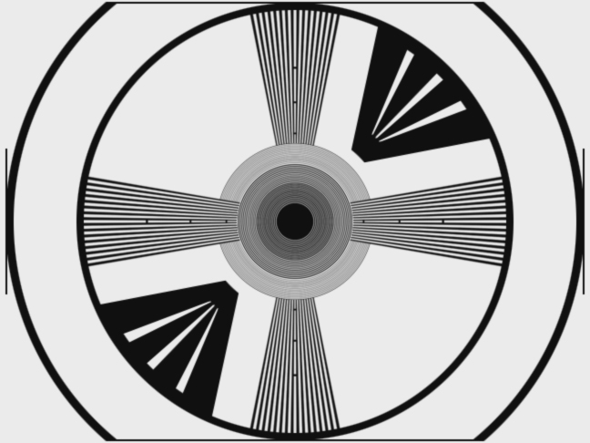 (Some stations used both Indian and RCA bullseye, namely KRLD Channel 4, now KDFW, in Dallas.) This pattern (albeit without the particular wedges on the top right and bottom left sides) was also altered with a few other elements by the stations of Crosley/Avco Broadcasting beginning in the late 1950's and in use at their TV stations (verified as at WLWT Channel 5, Cincinnati; WLWD Channel 2, now WDTN, Dayton; and WLWI Channel 13, now WTHR, Indianapolis). And who could forget the test pattern of CBS-owned and -affiliated stations, whose layout has been compared by DX'ers to an archery target: 
Last edited by W.B.; 04-11-2024 at 04:31 AM. Reason: Added WRIK-TV in 1962-78 test pattern section.
|
|
#6
12-27-2011, 11:54 PM
|
||||
|
||||
|
Here is a post that I made several years ago showing the 2F21 "Monoscope" CRT used to generate the "Indian Head" pattern. RCA would indeed provide custom versions of the pattern with call letters and perhaps other info printed on the target.
http://www.videokarma.org/showpost.p...5&postcount=29 jr
|
|
#7
12-28-2011, 12:58 AM
|
||||
|
||||
|
I use a Leader pattern generator most of the time. It has a small workbench footprint and works great. At other times, for various reasons, I may use the Sencore VA62 video analyzer, or a test pattern DVD, or (when feeling nostalgic and not very scientific) the BK 1077B TV analyst.
Phil Nelson Phil's Old Radios http://antiqueradio.org/index.html
|
|
#8
12-28-2011, 07:06 AM
|
||||
|
||||
|
I remember the color test pattern on WKBW. Oddly enough, it came on about a half hour before the station signed on the air in the morning. Before that, it was the typical color bars. I always thought, man, those TV repairmen that have to get their sets aligned sure do have to get up early in the morning!
__________________
"Restoring a tube TV is like going to war. A color one is like a land war in Asia."
|
|
#9
12-28-2011, 04:43 PM
|
||||
|
||||
|
So one would measure Horizontal resolution in terms of "lines per picture (vertical) height"? seems strange!
I would think that normalizing the measurement to CRT diameter/diagonal or width would produce data that would be more consistent... "portholes" got a big break with the "lines per picture height" definition. jr
|
|
#10
12-28-2011, 07:10 PM
|
||||
|
||||
|
Quote:
__________________
"Restoring a tube TV is like going to war. A color one is like a land war in Asia."
|
| Audiokarma |
|
#11
06-09-2012, 06:59 PM
|
||||
|
||||
|
Quote:
I used that generator to align my 25" Sony Profeel Monitor to get the minimum overscan possible when I bought it in about '87. Last year I put a tape of the test pattern on it and could see no change in picture size...
__________________
Mike Scott in SJ, CA Drive 'em to the XMAX!
|
|
#12
12-28-2011, 08:03 PM
|
||||
|
||||
|
Quote:
|
|
#13
12-28-2011, 09:42 PM
|
||||
|
||||
|
Aren't there always 525 lines (262 1/2 interlaced) vertical ? Minus a few for closed caption and other info that is.
|
|
#14
12-29-2011, 09:25 AM
|
||||
|
||||
|
Quote:
There are 525 total lines, but only 483 active lines due to vertical blanking. Let's just call it 480 for rough calculation (which also matches a common computer image format). Because the lines sample the picture vertically (just like the rows of pixels in a digital picture), they cannot provide a full 480 lines of resolution for ordinary pictures - they could only do that if the picture details happened to line up exactly with the line structure. The ratio of practical viewable resolution is called the "Kell factor" after Ray Kell, who published the original research in 1934. There is an additional factor due to interlace causing interline flicker - how strong this is depends on the observer and the amount of detail contrast in the image. The first NTSC (1941) adopted an over-all factor of 0.7 for the achievable resolution compared to the number of active lines. Along with this they specified a combination of baseband video signal bandwidth (4.2 MHz) and active scan lines (486) that would give equal resolution per picture height vertically and horizontally, and also fit in a 6 MHz channel using vestigial sideband modulation and including a sound carrier. 480x0.7 = ~330, the accepted usable resolution - your mileage may vary, and there have been a lot of useless arguments over the years as to whether the useful vertical resolution number is exactly correct. A few of the active lines were later devoted to other things like test signals, data, and closed captions, leaving 483 containing picture. Last edited by old_tv_nut; 12-29-2011 at 09:29 AM.
|
|
#15
06-16-2016, 09:28 PM
|
|||
|
|||
|
Quote:
|
| Audiokarma |
 |
|
|


 Hybrid Mode
