
|
|
|
#61
 04-24-2018, 12:50 PM
|
||||
|
||||
|
I t should be fine.... If you're still worried and have one of those TV magnifier accessories for 10/12" sets place it in front of the CRT and stand back a few feet...X Ray's are exponentially attenuated by air. Even if the CRT were a strong emitter once you get about 4 ft away the dose should be well within safe limits.
Another worry wart option would be to grab the leadded safety glass off of a color set and place it between the CRT and you.
__________________
Tom C. Zenith: The quality stays in EVEN after the name falls off! What I want. --> http://www.videokarma.org/showpost.p...62&postcount=4 
|
|
#62
04-24-2018, 01:09 PM
|
|||
|
|||
|
If there wuz anything to the Xray scare, all my kids should have two heads and six fingers.
 
|
|
#63
04-24-2018, 05:28 PM
|
||||
|
||||
|
25kv is starting to produce X-rays, and unlike color CRTs, that one most likely does not contain enough lead or thickness to reduce them. As said above, standing back several feet should be good enough protection. Also, X-ray effects are cumulative, so if you just have a quick look to see the shape of the circle, no problem. As an additional measure, you can turn down the brightness and run at much lower beam current for direct viewing.
|
|
#65
04-24-2018, 06:13 PM
|
||||
|
||||
|
Quote:
|
| Audiokarma |
|
#66
04-24-2018, 09:22 PM
|
|||
|
|||
|
Quote:
.
|
|
#67
04-24-2018, 10:35 PM
|
|||
|
|||
|
Hi Phil,
Your picture of the egg shaped vertical test pattern reminded me of the issue I had with my Stewart Warner 9100 mirror lid set. In order to correct it in my case I made a change to the RC time constant in the plate circuit of the vertical blocking oscillator. The original per Sams' was a 0.15mfd cap and a 2200 ohm resistor. I ended up using a 0.1mfd and 330 ohm resistor to get a balanced ellipse vertically. Increasing the width adjustment then made the the image circular. You made great progress.  Ed Last edited by EdKozk2; 04-27-2018 at 01:34 AM. Reason: typo
|
|
#68
04-26-2018, 07:22 PM
|
||||
|
||||
|
Quote:
For comparison, here's the previous test pattern: 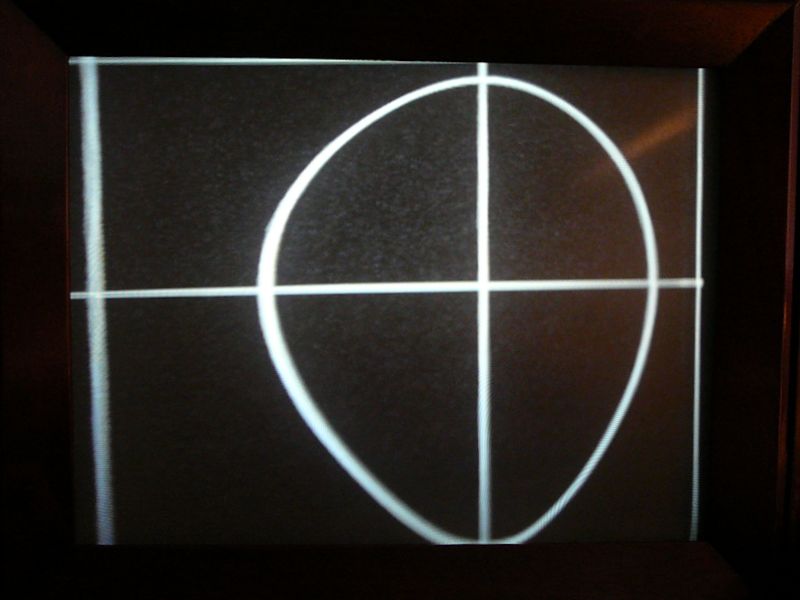 And here's today's pattern: 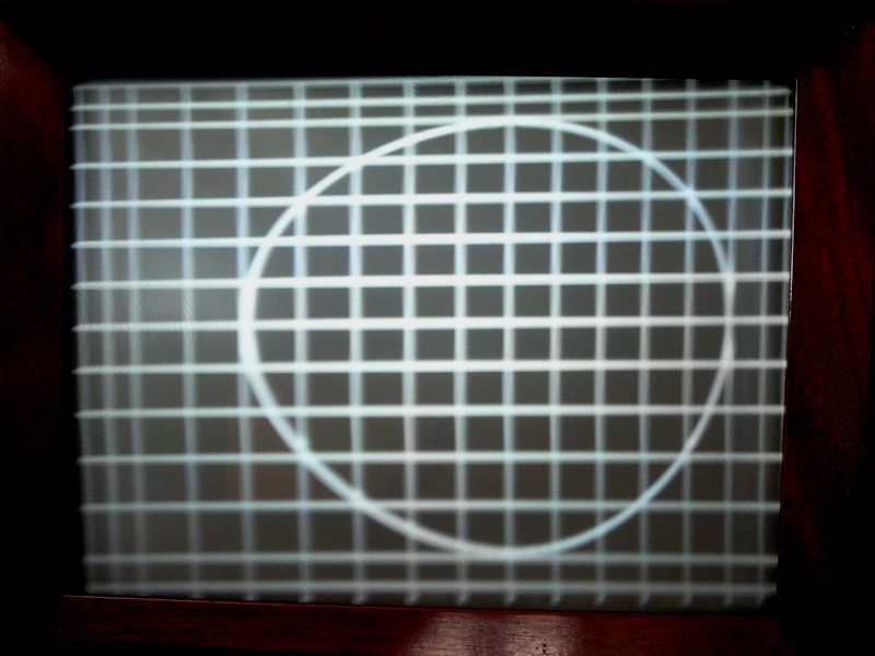 Not a great improvement, but something. It still feels like the horizontal circuits are just "off" in general -- the adjusters for horiz drive, horiz linearity, and horiz size are all maxed in one direction. The worst horizontal linearity is not at the far left edge, but in a band that starts maybe 20% in from the left edge. If you squeezed that band horizontally, you'd have a pretty watchable picture. Strangely, now it's easier to adjust for better vertical linearity. Phil Nelson Phil's Old Radios https://antiqueradio.org/index.html
|
|
#70
04-27-2018, 08:42 PM
|
||||
|
||||
|
Kindof a slow evening, and this thread caught my attention....
" Not a great improvement, but something. It still feels like the horizontal circuits are just "off" in general -- the adjusters for horiz drive, horiz linearity, and horiz size are all maxed in one direction. " I wonder, Could you post a picture however bad it may look with all those knobs set at mid-point...? Another goofy thought..... Is there any chance that the metal housing with all that optics has been magnetized...? I guess a quick answer might come if you looked at the picture outside all that optics..... But then I did read about your worry of x-rays.... With both H and V off in linearity, are the V lin and V height also maxed in one direction ? Seems like a voltage rail common to both H and V would be a good place to look. Looks like that will be a neat tv ! .
__________________
Yes you can call me "Squirrel boy" Last edited by Username1; 04-27-2018 at 08:48 PM.
|
| Audiokarma |
|
#71
04-27-2018, 10:03 PM
|
||||
|
||||
|
I decided not to mess with the optics until I have more faith in the electronics. Looking back at my notes, I saw several components still unchecked in the vertical & sync circuits. Plus, I want to check voltages in the sync & sweep circuits. The Sams manual doesn't show any oscilloscope waveforms, but the Riders manual includes a few, so scoping is also on the list.
Time to finish my homework, in other words, before I look for more exotic causes. The first resistor I checked today was a 3W dogbone style. It's spec'd at 10K and it measured at 24K (!). At first glance, you might think it's wirewound, but this just looks like a fat carbon rod with leads attached to the ends. Way out of spec, anyhow. I believe the vertical linearity control was also maxed. Not vertical size, though. Hope to spend more time on this over the weekend. Phil Nelson Phil's Old Radios https://antiqueradio.org/index.html
|
|
#74
05-02-2018, 09:42 PM
|
||||
|
||||
|
I thought Josef meant swapping the horizontal wires (pins 5 & 7 in the schematic) with each other and then swapping the vertical wires (pins 2 & 6) with each other. (In other words, not swapping the pair of horizontal wires with the pair of vertical wires.) Or am I misreading one or both of you?
Phil Nelson 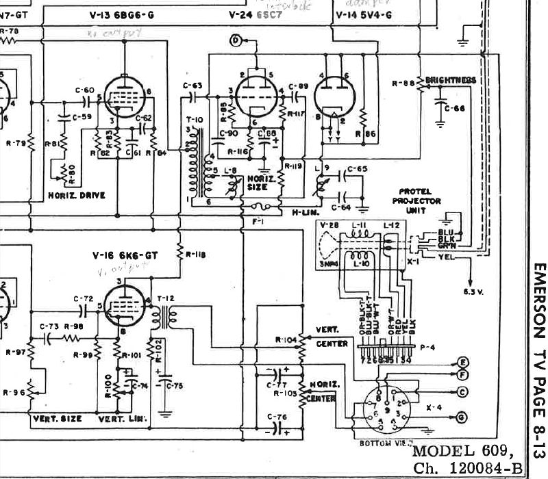
|
|
#75
05-02-2018, 10:23 PM
|
|||
|
|||
|
Hi Phil,
Just reversing the two horizontal wire connections within the same circuit is what makes sense. The same would go for the vertical connections. One thing to watch for is if the picture is reversed. Lettering or words on the final viewed image will be incorrect. Just like putting a slide in a slide projector backwards. Ed
|
| Audiokarma |
 |
|
|


 Linear Mode

