
|
|
|
#1
 01-29-2011, 11:17 PM
|
||||
|
||||
|
Philco 37-611 Restoration
While I wait for the paint on my Philco 60 to cure, I decided to try a quick restore of this Philco 37-611 AKA "Big Bullet" radio. There were a number of models in this cabinet style and I think this may be the lowest end. It's a transformerless 5 tube series strung set.
6Q7, 6K7, 6A8, 25Z6 and 25A6 although I found a 25L6 in it. That only adds up to 68 volts so there are two resistors to burn off the rest. The cabinet appears to have been refinished in polyurethane and no grain filler. There's a chip in the veneer and this ugly repair. You'd think they could have at least used a little stain! I suspect the grille cloth is a replacement. 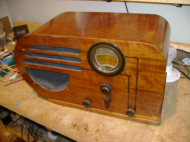 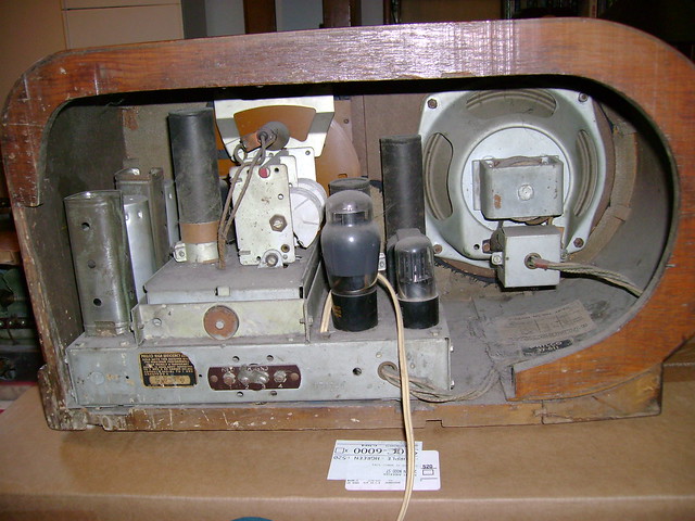 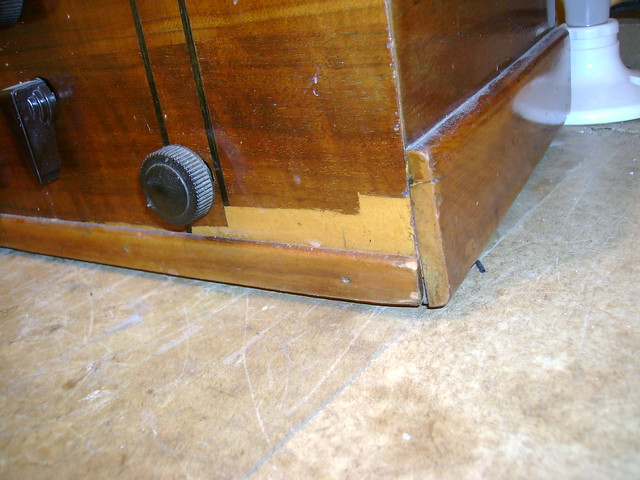 The chassis and dial are in good condition. The AC cord was replaced at some point. Also an electrolytic was added below. I was happy to find all glass tubes rather than metal as it would have had originally. 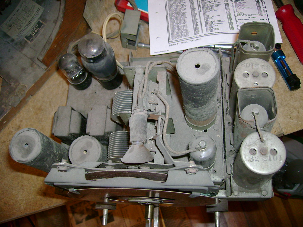 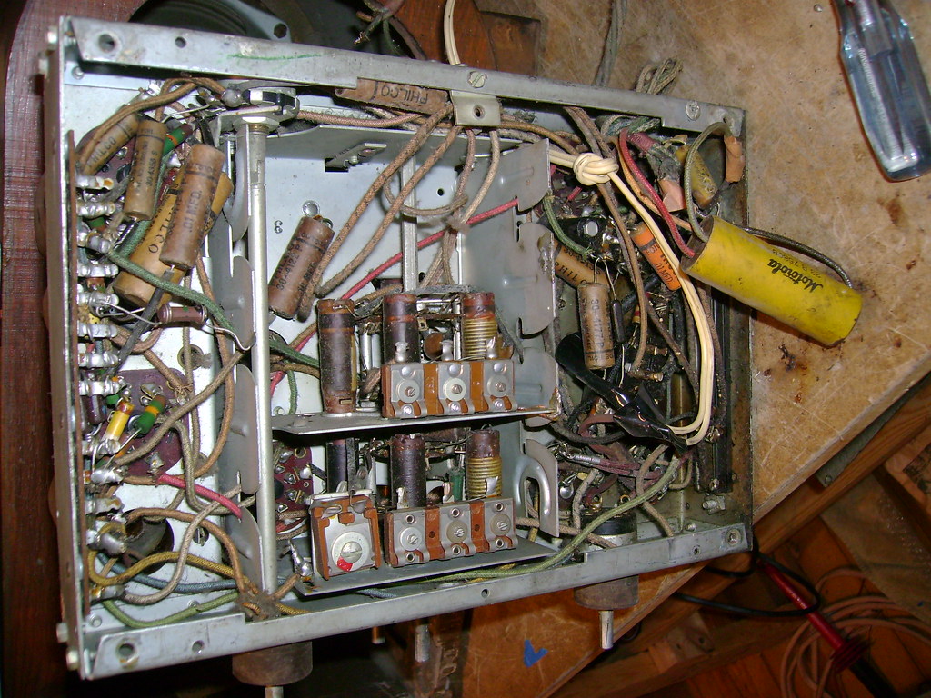 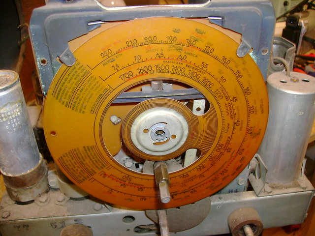 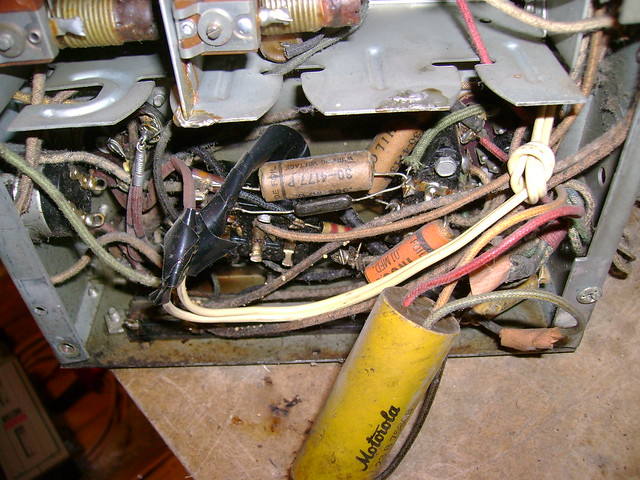
Last edited by bandersen; 01-29-2011 at 11:22 PM. 
|
|
#2
01-29-2011, 11:37 PM
|
||||
|
||||
|
You may have to add a resistor if it had one of those heater cords. One of my Air Kings were fitted with an adjustable wirewound after a cord replacement many years ago.
|
|
#3
01-30-2011, 07:23 AM
|
||||
|
||||
|
I have had good luck replacing resistor droppers with non-polar capacitors. They don't heat up and also give the heaters a soft start. Non polarized caps are often available from Goldmine, and also may be used Cornell Dubilier DME poly film large value caps from the usual large suppliers.
http://www.vintage-radio.com/repair-...per-calcs.html
__________________
Reece Perfection is hard to reach with a screwdriver.
|
|
#4
01-30-2011, 04:12 PM
|
||||
|
||||
|
Thanks for the link - good food for thought. I wonder how well a single diode would work since I need to burn off just about half the voltage ?
The existing (huge) two-section dropping resistor tests OK, so I'll use that initially. I'm curious to see how hot it gets.
|
|
#5
01-30-2011, 05:11 PM
|
||||
|
||||
|
Never tried the single diode approach. If I were to try it I'd bring the set up on the variac while monitoring heater string voltage to see if it "really" worked. I do like the cap method since you get a soft start and about a 20 second ramp up to full voltage.
__________________
Reece Perfection is hard to reach with a screwdriver.
|
| Audiokarma |
|
#6
01-30-2011, 07:54 PM
|
||||
|
||||
|
To do the diode trick, the heater string voltage needs to add up to about 85V. Not 60V. Because Power = (volts squared)/resistance. The diode cuts the power the resistance of the heater string gets by 1/2. It turns out that (85^2)/R=(1/2)(120^2)/R
If you're short on the 85V for the heater string, you can pad it some with a power resistor. Even so, you avoid a lot of waste heat. Quote:
__________________

Last edited by wa2ise; 01-30-2011 at 08:03 PM.
|
|
#7
01-30-2011, 08:17 PM
|
|||
|
|||
|
Quote:
They always used Candohm dropping resisters.
|
|
#8
01-31-2011, 05:24 PM
|
||||
|
||||
|
I'm done replacing all the paper caps except for these two buried in the tuner sub-chassis. The one on the left is an oddball dual 0.05 uF cap.
Any ideas on reaching them other than removing the sub chassis ? I don't think that would be much fun to try  
|
|
#9
02-01-2011, 07:22 AM
|
||||
|
||||
|
Those caps: you may be able to clip the leads leaving a stub and then form curls in the leads of the new cap and implant them, solder with a pencil iron.
__________________
Reece Perfection is hard to reach with a screwdriver.
|
|
#10
02-01-2011, 12:42 PM
|
||||
|
||||
|
Quote:
__________________
|
| Audiokarma |
|
#11
02-02-2011, 03:19 AM
|
||||
|
||||
|
The problem with both those caps is that one end is deep into the subchassis. Deep enough that none of my tool can get in there. So i just left them in for now and completed work on the rest of the set.
I rebuilt the two bakelite block caps and removed all traces of the earlier repairs. That included putting some resistors back to the values indicated in the schematic. For example the 400 ohm cathode bypass on the output tube had been reduced to 150. I put a 390 in. I didn't restuff the electrolytics though. I may someday, but I thought it's be nice to get a radio playing in a few days rather than the weeks I usually spend on a project  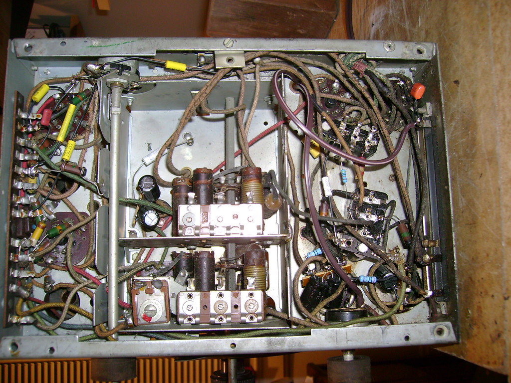 I did a simple check by hooking an ohmmeter across the AC plug and turned it on. Nuts - it measured infinity. I traced through the wiring and found that the power switch / tone control is fried. I temporarily jumped that and the resistance measure about 190 ohms - pretty much what I expected. Next, I powered it up through a dim bulb setup. The bulb lit up bright. I removed a tube and the light went out. That seemed odd so I started testing the tubes and found the 25Z6 had a cathode short. Ugh! So these have the same flaws as 6X5s ? I bet that took out the power switch too. I dug up a good one and tried again. This time I was treated to talk radio once it warmed up  Reception is pretty good on AM and I did pick up a few shortwave transmissions. There are 4 antenna terminals on the back and I'm not quite sure which one to use for each band. I'll play around with it more tomorrow. Reception is pretty good on AM and I did pick up a few shortwave transmissions. There are 4 antenna terminals on the back and I'm not quite sure which one to use for each band. I'll play around with it more tomorrow.That AC ballast resistor does get pretty toasty so I will look into replacing it using the tips above. 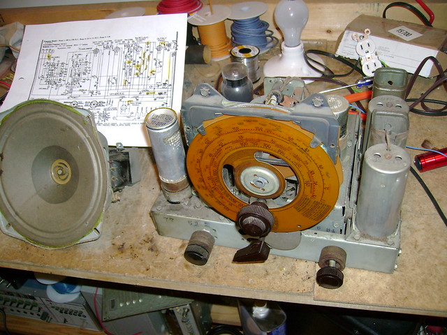  
Last edited by bandersen; 02-02-2011 at 02:42 PM.
|
|
#12
02-02-2011, 02:51 PM
|
||||
|
||||
|
You could also drop the some of excess voltage by substituting 35 volt versions of the 25 volt tubes & 12 volt for the 6 volt - examples: for 25Z6 use a 35Z6 & for 6Q7 use a 12Q7.
I have done this to radios when replacing a resistive line cord with a standard cord.
__________________
Bruce Last edited by MAGICBRAIN; 02-02-2011 at 02:58 PM.
|
|
#13
02-02-2011, 03:35 PM
|
||||
|
||||
|
Quote:
Could I use a 50L6 in place of the 25L6 output tube 
|
|
#14
02-03-2011, 08:03 AM
|
||||
|
||||
|
Be careful about swapping 12V tubes out for 6V tubes. The 6V tubes generally draw 300mA on the filament while the 12V tubes draw 150mA. Same thing between a 25L6 and 50L6.
__________________
Sean - WØKPX
|
|
#15
02-03-2011, 12:08 PM
|
|||
|
|||
|
Quote:
|
| Audiokarma |
 |
|
|


 Linear Mode

