
|
|
|
#31
 03-06-2012, 10:43 PM
|
||||
|
||||
|
Oh yes, I'm very happy that it's working. So many other things could have gone wrong like the hacked up power and output transformers.
I took a whack at retuffing the can caps tonight. I was surprised at how easy it was to cut them open with just a sharp utility knife and gently rolling action. Even more surprised at how much liquid came out. I'm glad I had some napkins handy!   I soldered on some extension wires and threaded them through the hole at the bottom. Then popped the tops back up, mounted and wired them in. That just leaves one non Philco cap. Anyone have a spare 30-2330 (8mfd, 400v) ? Or anything close that would fit.  

|
|
#32
03-10-2012, 03:10 AM
|
|||
|
|||
|
My power transformer was bad, and I had trouble finding a replacement by the Philco part number. But I determined the specs and found a cross-match in one a fellow radio club member gave me. I verified the specs through testing the transformer's resistance and voltage readings:
It is an RCA part with number 970445-1 printed on the case. It matched the voltages of the Philco 32-7976 at 250-0-250 and 6.3v, and even the bolt holes lined up without chassis modification. Perhaps someone else wanting a transformer for a Philco 39-30 will find this cross-match useful.
|
|
#33
03-13-2012, 07:18 PM
|
||||
|
||||
|
Thanks for the info.
It's pushing 80 in my attic so I'm able to spray in mid March. Crazy! 
|
|
#34
03-30-2012, 09:06 PM
|
||||
|
||||
|
I'm finally just about done with this set!
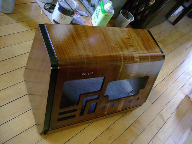 I painted the edges around the speaker by hand with dark paint. 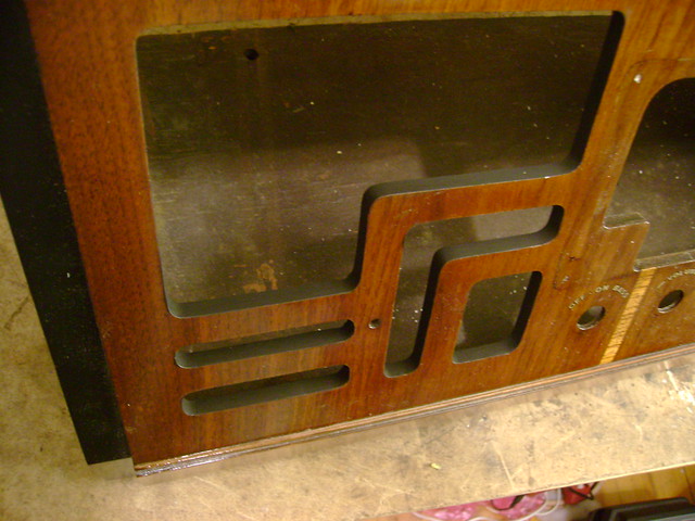 The radio came with these long "U" shims under the chassis. I wonder if they are factory or were they a later addition to compensate for mushed down rubber corner mounts ? I've replaced the old mounts with reproductions and the shims seem redundant now. Has anyone encountered these before ? 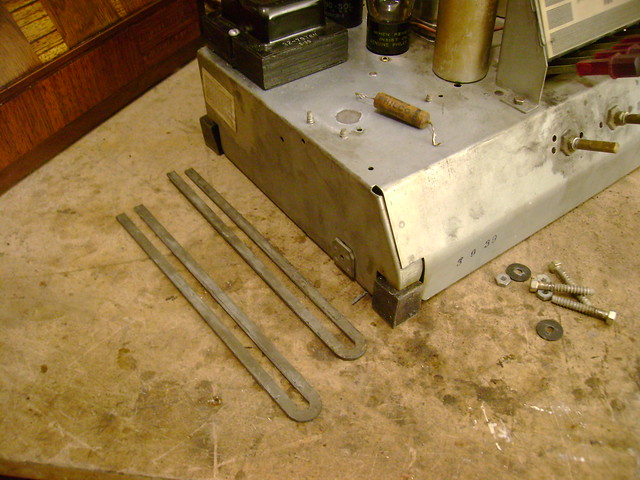
|
|
#35
03-31-2012, 10:55 AM
|
||||
|
||||
|
This has turned out really sharp. Excellent hand work around those speaker grille openings.
Never seen those shims on a Philco before, but it's curious how they happen to be almost perfect in length for that chassis.
|
| Audiokarma |
|
#36
03-31-2012, 12:36 PM
|
|||
|
|||
|
As usual, an excellent restoration job. Those shims are probably shipping shims that no one bothered to remove.
|
|
#37
03-31-2012, 03:13 PM
|
||||
|
||||
|
Quote:
This is just a guess, but I'd say they were factory equipment, just on a different radio. Just judging by similar systems I've seen in the past, I'd suspect their original purpose was to work as a guide for reinstalling a chassis... they were probably secured to the interior bottom of the cabinet in some way, maybe in a recessed channel, and the matching chassis would have had some sort of nuts or bushings along the bottom edge that would have slid in between the forks and provided a quick and easy way to line up the screw holes.
|
|
#38
04-06-2012, 05:12 PM
|
||||
|
||||
|
I spent a couple days rubbing out the cabinet and boy are my arms tired!
I hope to finish off this project later tonight  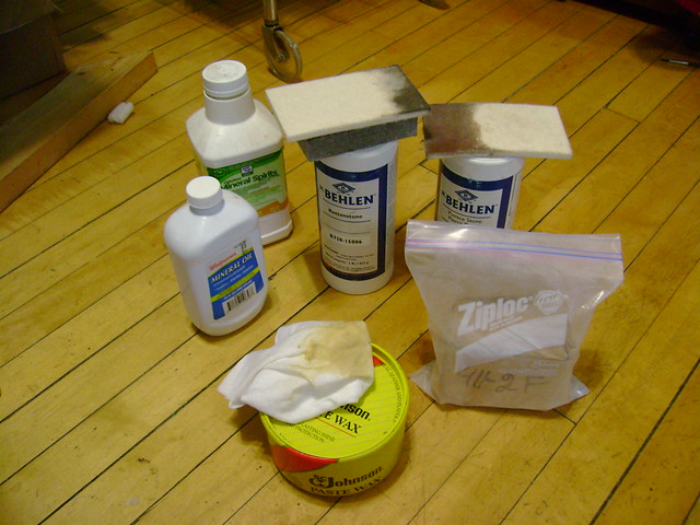 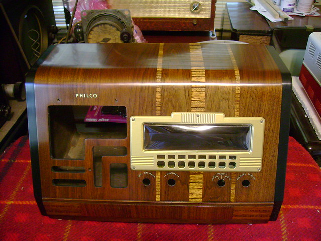
|
|
#40
04-06-2012, 11:51 PM
|
||||
|
||||
|
Thanks!. I think it's my best cabinet restoration so far. Soon I may feel up to finally tackling my 15DX
At long last, it's a wrap  The only thing left is to print out some station preset inserts. The only thing left is to print out some station preset inserts.In retrospect I'm kind of amazed it's working at all considering the rotted wiring, open output transformer etc... BTW I left the U channel shims out and the chassis lines up fine. 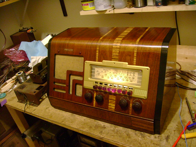
|
| Audiokarma |
|
#41
04-08-2012, 12:03 PM
|
|||
|
|||
|
Truly the work of a perfectionist!
|
 |
|
|


 Linear Mode

