
|
|
|
#46
 06-03-2015, 09:13 PM
|
||||
|
||||
|
Is there any way to stand (or brace up) the chassis on its side behind the cabinet and connect up using the original cables?
 I realize your chassis isn't designed to stand up that way, but if the connectors would reach, that might be a way to access the underside while it's powered up. Just an idea . . . . Phil Nelson Phil's Old Radios http://antiqueradio.org/index.html 
|
|
#47
06-04-2015, 01:32 PM
|
|||
|
|||
|
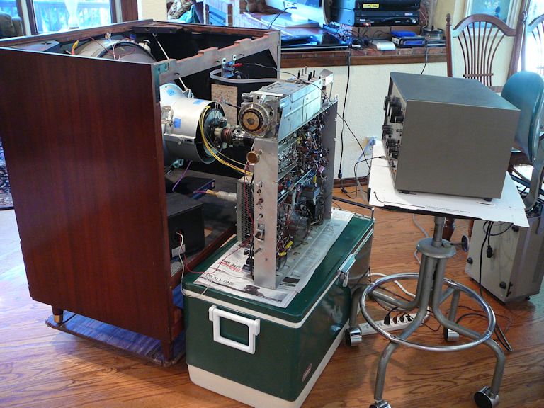
Good suggestion Phil, and I even have a cooler just like that to sit it on. It just might work out for me. Maybe I could like tie a string, or something to brace the chassis to it stands up like yours, seems as it if would work. Thanks for the picture.
|
|
#48
06-04-2015, 07:10 PM
|
||||
|
||||
|
During part of my CT-100 project, I stood the chassis sideways on a square of heavy plywood. I screwed one end of a diagonal brace (a wooden stick) to the plywood and lashed its top end to the upper part of the chassis. That allowed me to make measurements & adjustments with the underside of the chassis exposed.
Tube extenders let you make many voltage measurements from above, when the chassis is in the cabinet, but if I recall correctly, there were some tubes under the CRT without enough vertical room to take an extender. I use a second cooler with a folded quilt to make a seat behind the chassis. Phil Nelson
|
|
#49
06-04-2015, 09:11 PM
|
||||
|
||||
|
It makes more sense to remove the yoke and put the chassis on the bench. You can then work your way through it, using a scope, to make sure everything is working. Then put the yoke and chassis back for final test.
|
|
#50
06-04-2015, 09:18 PM
|
|||
|
|||
|
Both of you Phil and Steve have very good ideas. I sort of like to see whats on the screen as I work on it, but I also understand that it is much easier on the bench. I am concerned about the yoke only in the sense that the cover is crumbling, and I believe there was a post about how to make one using something common, such as a plastic lid, or something. Of course the crumbling yoke covers were common on all of the old sets, even B&Ws as well.
|
| Audiokarma |
|
#51
06-04-2015, 09:47 PM
|
||||
|
||||
|
Quote:
http://videokarma.org/showthread.php...=21ct55&page=2 The cover fit on the yoke nicely. I made three small holes to allow the rivets on the shield that mounts on the back of the cover to snap into the cover. I did my initial powered testing on the bench with the yoke plugged in but no CRT connected. I made many quick powered checks with the HV loaded by a 40KV HV probe. Once all the voltages, currents, and waveforms looked right I put the chassis back into the cabinet laying it on its side to get at the bottom of the set. Dave Last edited by Zenith6S321; 06-04-2015 at 09:53 PM.
|
|
#52
06-04-2015, 10:01 PM
|
||||
|
||||
|
Quote:
That's a nightmare! No matter how carefully you mark a CT-100, you will never ever get the yoke tilt the same, so you will have to start convergence from scratch. Perfect convergence is possible but the yoke position is critical to the millimeter, including the tilts. I don't know if this applies to 21axp22 sets. I know I never got my college roommate's CTC5 or 9 anywhere near as good convergence, but they of course don't have tilts.
|
|
#53
06-05-2015, 06:08 AM
|
||||
|
||||
|
Two other ways to work on the chassis:
Everything on the chassis except the AGC, sweep, and HV will work without the yoke. You need to put a jumper in the yoke socket to connect the B+, though. You will need a bias box to set the AGC voltage. That will allow you to get almost all the circuits working before putting it back in the cabinet. Make a yoke extension cable and leave the yoke in the cabinet.
|
|
#55
06-07-2015, 11:05 AM
|
||||
|
||||
|
Or do what I did and break apart any octal tube to harvest the socket, and use that as your B+ jumper. All you need to do is connect the appropriate pins, and you'll have power to all the circuits. Just make sure you NEED power to all the circuits! It works on all the early CTC chassis.
__________________
Evolution... 
|
| Audiokarma |
|
#56
06-07-2015, 11:58 AM
|
|||
|
|||
|
The other RCA roundie in the picture is my CTC9 1959 Model
Quote:
The other roundie is a CTC9, model 210CK924. It looks pretty good, but still needs some work. Set has low hours and has the original 21CYP22 CRT. Right now (as of yet) it is running with the original filter cans, which I still intend to replace with modern caps, although they do run fairly cool. It still has a problem with the vertical and horizontal sync at times, and the vertical height has a tendency to collapse. (I believe there is a broken ground somewhere on the vertical/horiz circuit board) Cabinet is in perfect shape, no scratches, back and everything is complete and the set when I got it was super clean inside for it's age. I obtained this on Craigslist from Blair NE. I have another post on here somewhere about the set.
|
|
#57
06-20-2015, 06:37 PM
|
|||
|
|||
|
Progress on the CTC2B, 21CT55, 21 inch roundie color from 1954
Some progress on this set, the CTC2B, 21CT55, from 1954. I removed the chassis, yoke, and convergence assembly. The set looks to be in really good shape, and it looks to be a low hours set. Yes, there is some rust on the tube shields, but other than that, it's clean, even the flyback looks really good, just a small amount of wax drippings. Here are some pictures of the chassis before recapping, and cleaning. Even the resistors don't seem to be discolored with heat and age. Next for me is the tedious task of recapping, checking tubes, cleaning, and replacing several peaking coils that are open.
|
|
#58
07-04-2015, 04:04 PM
|
|||
|
|||
|
Just to let you guys know why there hasn't been any more progress of restoring this 21CT55, CTC2 1954 color. I hurt my back moving a heavy piece of equipment about a month and a half ago, and I've been sort of laid up as far as getting things done. I herniated (sliped disc) in my back and it causes me a lot of back pain, and also burning pain down my legs. I have been taking pain pills and steroids for it, and also got shots of cortisone into my spine, which have helped, and also doing certain exercises to get my back into shape again. The spine doctor seems to think everything can get me back to near normal without doing risky surgery. Also have been seeing a Chiropractor. I do have the chassis removed and cleaned up, tested the tubes, (4 bad), and ohmed out the convergence transformer which has continuity on all of the windings, which is a good thing. It seems as if nearly all the white coated peaking coils are open so have to find the values and order them. Next is ordering the necessary caps, and other parts, as I am getting back into action. I sure hope I can get a good picture on this set when everything gets done. I believe it will be an on going (probably a 2 year) project.
|
|
#59
07-04-2015, 05:27 PM
|
|||
|
|||
|
I herniated disc in 2007 after a marathon auto repair procedure. I went to a Physical Therapist and followed her recommendations religiously. I didn't have to have surgery. I still don't lift heavy loads, but otherwise I'm back to normal.
Best of luck with your recuperation. and restoration.
|
|
#60
07-04-2015, 05:32 PM
|
|||
|
|||
|
In the pictures in Post #57, I noticed the name Glaser Steers Corporation on the convergence coil assembly. I remember Glaser Steers as the name of a high end record changer company. Most notable was the fact this record changer stopped the turntable when the next record was dropped. Quite a sight to watch in operation.
|
| Audiokarma |
 |
| Thread Tools | |
| Display Modes | |
|
|


 Linear Mode

