
|
|
|
#1
 08-09-2015, 01:00 AM
|
||||
|
||||
|
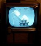
1949? Motorola 10VT24R, TS-14B chassis
Hey ya'll, It's been a little while. Well I thought I was going to be getting to my Zenith SC, but the space I had reserved for pulling it apart in is not available anymore at the moment, and like I said before, I'm not dragging it down to the basement. For now, It'll wait.
 Anyway's, after recapping some radio's, I've decided to get into this set. It's allready got an issue. Well, what's new about that.  So far, I've replaced all the Electrolytic caps, some paper that looked suspicious, and some that were clustered together around the suspicious one's since I was on a role... I have more to go. I also allready swapped the celenium's for 1N4007 diode's. Unfortunatly I dont have a schematic to go by for this one. It's on ETF's site but it's too hard to read...http://www.earlytelevision.org/pdf/m...4_manual.pdfSo i've been going with what's in the set since it was complete and didn't look burnt. Well, I tried a power up and... blew an E-cap   It was only at 30V!... It was only at 30V!...I also found that none of the tubes had lit up(all are good) and I had really heated up another e-cap. Both of these caps are connected to the diode's. The diodes are wired in the same as the celeniums were. positive-negative wise. I never added any resistors too them. (I don't know if they need them or not.) The cap that blew was a replacement for 140mfd/150v. I had 147mf/160v in place and it heated the 100mfd/300v cap up. Nothing that I could see was shorted out on another component, so why would it do this with only 30v being introduced into the set??? some pics. Note: I know my e-caps look like a mess, but nothing is touching what it shouldn't be. I also have pictures of what I beleive is a capacitor. Is that the value on the backside or a part# that looks like a cap value? I havn't come across capacitors that look like that one yet. 
|
|
#2
08-09-2015, 01:19 AM
|
||||
|
||||
|
Well usually for a cap to blow like that the polarity has to be backwards.
From what I can see in your picture you have the positive of the Diode going to the chassis ground and the negative going to the positive of the cap?
|
|
#3
08-09-2015, 01:36 AM
|
||||
|
||||
|
The angle of that photo is a little misleading.
The one that blew(147/160v) is connected at the positive and negative of the 2 diode's. The positive of one diode then goes to the 100mfd cap+ and the negative of the other goes to the 2nd e-cap can ground. (I kept the cans as the ground points, and only disconected the positives of them.) Quick question, the negative of the diode's is the side with the line right? Last edited by ZackN920; 08-09-2015 at 01:41 AM.
|
|
#4
08-09-2015, 02:43 AM
|
||||
|
||||
|
No, the Positive of the Diode is the end with the line.
That one marked .047 400 is a cap, a paper type, not electrolytic. .047 Micro farads at 400 volts, a higher voltage can be used but the .047 must stay the same.
|
|
#5
08-09-2015, 10:16 AM
|
||||
|
||||
|
The diode conducts when the end with the line is negative.
This means that when used as a rectifier, the end with the line is the plus end. That obvious diode has the correct end to ground. I do suggest that if you leave that mess as-is, use plenty of vinyl tape! I've been known to do that. Its not OK, well it IS perfectly OK electrically, just leads to nasty comments on Videokarma.
|
| Audiokarma |
|
#6
08-09-2015, 11:26 AM
|
||||
|
||||
|
Quote:
This article has basic information about identifying old capacitors and choosing replacements: http://antiqueradio.org/recap.htm Regards, Phil Nelson Phil's Old Radios http://antiqueradio.org/index.html
|
|
#7
08-09-2015, 11:37 AM
|
|||
|
|||
|
I can't find the schematic anywhere, but if the B+ supply uses a standard doubler circuit, it should be one of the two configurations shown here..
http://www.electronic-circuits-for-h...-two-diode.php The banded end of the Si diode denotes the cathode. Seleneums frequently had a '+' sign denoting the cathode, which is counterintuitive as hell. But that was the convention.
|
|
#8
08-09-2015, 12:59 PM
|
|||
|
|||
|
hi, Check front cover of the Motorola manual you will see that it is for chassis,TS-14,TS-23 and TS-52. Photofact for all three is 92-4. ETM does have a scan of that photofact. All the best, tom.j.fla
Last edited by tom.j.fla; 08-09-2015 at 06:55 PM.
|
|
#9
08-10-2015, 01:03 AM
|
||||
|
||||
|
Thanks guy's for the info about the diodes. I didn't realize that when used as rectifiers that ya essentially swap there polarities. I had them in backwards for that funtion.
Hey Phil, when I talked about the suspicious caps, they looked plain bad. Side popping out if the one, another had the lead pop off when moved,yadayadyada. hey Tom, I'll have to look that up on a PC. It doesn't seem to want to work on the IPod touch. Anyway's I put new E cap in place of the blown 147/160v unit. Also checked the diodes and they test good. I rewired them how they should be. Should I replace the 100mfd cap as well? It got hot but didn't ooze it's guts. I decided to try another power up. Had the dim bulb tester on it this time. Everything OK, so I upped the power and got a raster. In the form of a 1.5 inch horizontal line on the screen. I couldnt get it to fill the screen. Well, I replaced most of the paper caps. Still have 3 bumble bees by the gang of e-caps. I decided to power it up again. Same basic response, except I seem to have better sound now,more shush since it has no incoming signal. No real improvement in the image. Still can't get it to fill the screen. My vert output tube is good. It's also wavy (like 60hz interferance) so Mabey that 100mfd is f'd up. I also noticed something I find very odd. The picture is it's brightest at about 85volts. When raised to 110v, the picture goes very dim. I have no clue what the deal with that is!? That's where I'm at so far. Whatcha y'all think?...
|
|
#10
08-10-2015, 02:06 PM
|
||||
|
||||
|
I think that you should really get the rest of the caps replaced before you go any further. Replacing the seleniums with diodes but leaving *any* capacitors un-replaced in a set of this age is doing it backwards IMO.
__________________
"Restoring a tube TV is like going to war. A color one is like a land war in Asia."
|
| Audiokarma |
|
#11
08-10-2015, 02:16 PM
|
||||
|
||||
|
Be aware that I worked on my TS-14 for sync troubles for a long time and got nowhere! I had replaced the seleniums with 1N4007 diodes and the B+ was too high. I added resistance in line with the diodes and got the B+ where it should be and the sync was fine. Replace the caps in the horizontal oscillator stage. If there are leaky ones the set goes nuts! Other than that, these are reliable sets and have a great picture!
|
|
#12
08-10-2015, 02:18 PM
|
||||
|
||||
|
Quote:
jr
|
|
#13
08-10-2015, 02:26 PM
|
||||
|
||||
|
Quote:
But jr_tech is right. You're asking for trouble leaving those bumblebees in there. I'm by no means the last word on TV restoration, but it's been my experience that you can't leave any of that stuff in there and expect the set to work long term.
__________________
"Restoring a tube TV is like going to war. A color one is like a land war in Asia."
|
|
#14
08-10-2015, 08:37 PM
|
||||
|
||||
|
As a rule if a cap gets warm or hot in operation (assuming a power tube is not really close and heating it up) THEN IT IS A BAD CAP, if you wait until they blow their guts odds are other possibly unobtainium parts are going to be killed by them.
__________________
Tom C. Zenith: The quality stays in EVEN after the name falls off! What I want. --> http://www.videokarma.org/showpost.p...62&postcount=4
|
|
#15
08-10-2015, 11:16 PM
|
||||
|
||||
|
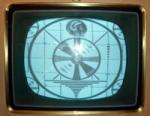
Ok, the bumble bees are gone,(There was no plan to keep them) and so is that 100mfd E-cap. That cap's replacement looks worse now(3capscombined) but at least I don't have to worry about it. The "general" recap seems to be complete. No more old papers(bb,or those plastic ones) and no old E-caps.
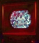
Hey Zenith26kc20, Do ya remember what the ratings of your resistors were? I'm not sure how to figure it. Kamakiri- I saw in the Sams mentioned above http://www.earlytelevision.org/pdf/M...-Sams-92-4.pdf and the only spec is the current rating, which is .225A for both. I don't know what to do with that info. After working more this evening, I powered it up again. All is the same...  Well, at least it seems stable. Nothing burned up or changed in the 15 minute long power up. Well, at least it seems stable. Nothing burned up or changed in the 15 minute long power up. I'm still dumbfounded with it losing brightness when the power is raised to line voltage. And I can't get it to fill the majority of the screen. Only have a 1.5"-2" horizontal line. I noticed if I turn the horiz hold more than 1/3 counter clockwise this thing just SQUEALS. I also notice that if I messed with the vert.lin or size(cant remember which), and put the control in the middle the screen would bounce into the thin horizontal line, then it will go back to the 1.5" line without changing the control...hmmm this thing sure is strange  Thats where Im at so far... heres a picture!!!
|
| Audiokarma |
 |
|
|


 Linear Mode

