
|
|
|
#1
 03-29-2024, 09:35 AM
|
|||
|
|||
|
Dumont RA-103 Project Redux
Hi Folks,
I'll be restarting this one again. I got a NOS delay relay installed and working Last power up, I had smoke from the area of the vertical output transformer. After much analysis revealing the value of a VTVM in testing coil winding integrity, I found no damage to the VOT. This doesn't mean I'm certain this was the source of the smoke...just that it was coming from this area. I sourced a new 1Kohm focus rheostat from Surplus Sales. I'm going to install it on the back of the chassis as the shaft is not long enough for a direct replacement. Tom C. gave me some advice on extending this but I can't remember what he said and I'm too lazy to search for it!!!! So I'll be on a journey through this in the next few months and I hope you will be along there for the ride. Just wanted to get things started! 
|
|
#2
03-29-2024, 07:19 PM
|
||||
|
||||
|
I believe ACE hardware sells 1/4" shaft couplers...if the new shaft sticks out close to 3/8" or more one should work...just saw the shaft off the old pot after measuring how far it sticks out and stick it in the other end of the shaft coupler (and make sure it sticks out the same length as the old one did). If ace doesn't have it Amazon or some online vendors will. You can get rigid and flexible shaft couplers...This application is probably better with the rigid kind. (Last spring ETF I turned down a nice doghouse because someone had deleted the focus knob and put on wrong knobs elsewhere and I thought it looked real bad like that).
I forget where the vertical output transformer is but if it's near the candohm chassis mount power resistors those are more likely to be the source of the smoke....I haven't had any fail for me, but of the 5 RA-103s I've had 3 of them had 40s-50s power resistors cobbled in to replace those resistors or sections of them. The one near the vert osc transformer (and the osc transformer itself) are common to find failed.
__________________
Tom C. Zenith: The quality stays in EVEN after the name falls off! What I want. --> http://www.videokarma.org/showpost.p...62&postcount=4 Last edited by Electronic M; 03-29-2024 at 07:22 PM.
|
|
#3
03-30-2024, 05:31 AM
|
||||
|
||||
|
Last time I was at Moyers, I started rattling off the values of power reaustors I needed for my 30s GE table radio.
Before I was done, he interrupted me and said “Candohm?” Those things are famous for shorting and going open, and in general, just foung annoying stuff.
|
|
#4
03-30-2024, 11:24 AM
|
|||
|
|||
|
OK here we go. Let me preface this with two things because in the past, when I have posted pictures of work that I have done, I've received a few nasty comments about lousy soldering, poor organization etc. I started this hobby in late 2020 and there's no question some of my restorations have looked amateurish. I'm 64 years old now with shaky hands. Despite this, most of my electrical work is solid and reliable. I by no means try to pass myself off as an experienced electronics restorer. Constructive advice is always welcome, in fact, it's desired but I'm sure some here will not participate or lose interest when the journey reveals stupid mistakes or poor technique. So be it. I desperately want to get this TV working but it was altered significantly by previous work over decades and I've done my best to attempt to problem solve. With all this in mind, I'll make my second point.
I started work on this TV a couple of years ago when I had a significantly different approach to restoration. Today I use the standard method of trying to baseline the TV through a slow power up on original parts. Once that's done, I do methodical replacement of components where I think the failure points are and then check function. But a few years ago, I shotgun recapped my restorations and I had a reliable bookkeeping method but I did create errors that were then difficult to run down. That's the method I used and describes the current state of this TV. I have some rudimentary function in the relay/rectifier section but then I start to hit walls. I had the great fortune to run across this on eBay and snatched it up.  This was a great acquisition because of the quality of the available resources. I can't read the Sams schematic. The copy quality is poor and the print is microscopic. The Riders service data is much more useful and I've been using it as an adjunct to the publication above. Below is the Dumont Service Manual schematic for the RA-103  Below is the detail of the section I have had success with. The relay works and the circuit closes powering the entire TV 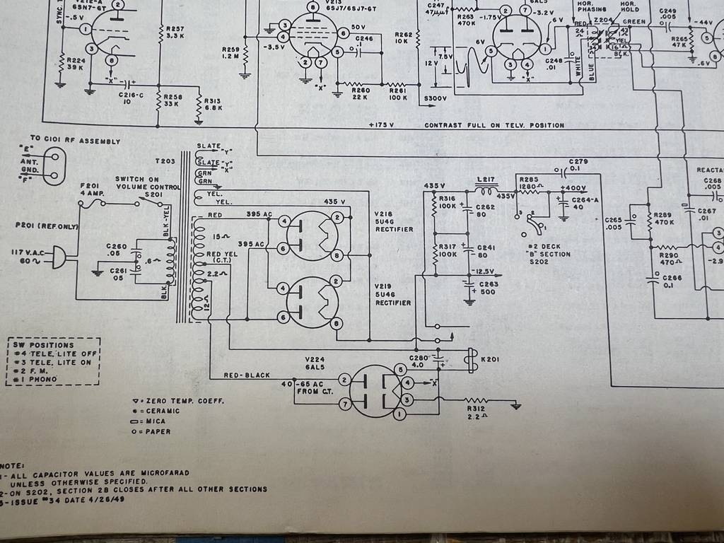 OK, here are some pictures of the chassis. I did relocate the focus pot and I am in the middle of wiring it up. It's mounted on the side of the rear of the chassis under the HV cage. The wiring in the rectifier section is a mess and I will clean it up. I tested function on 4 relays so there was a lot of extension wiring to test it unmounted. Oh hell...I'll just post them all! Go ahead, let me have it!  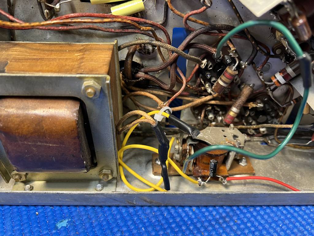 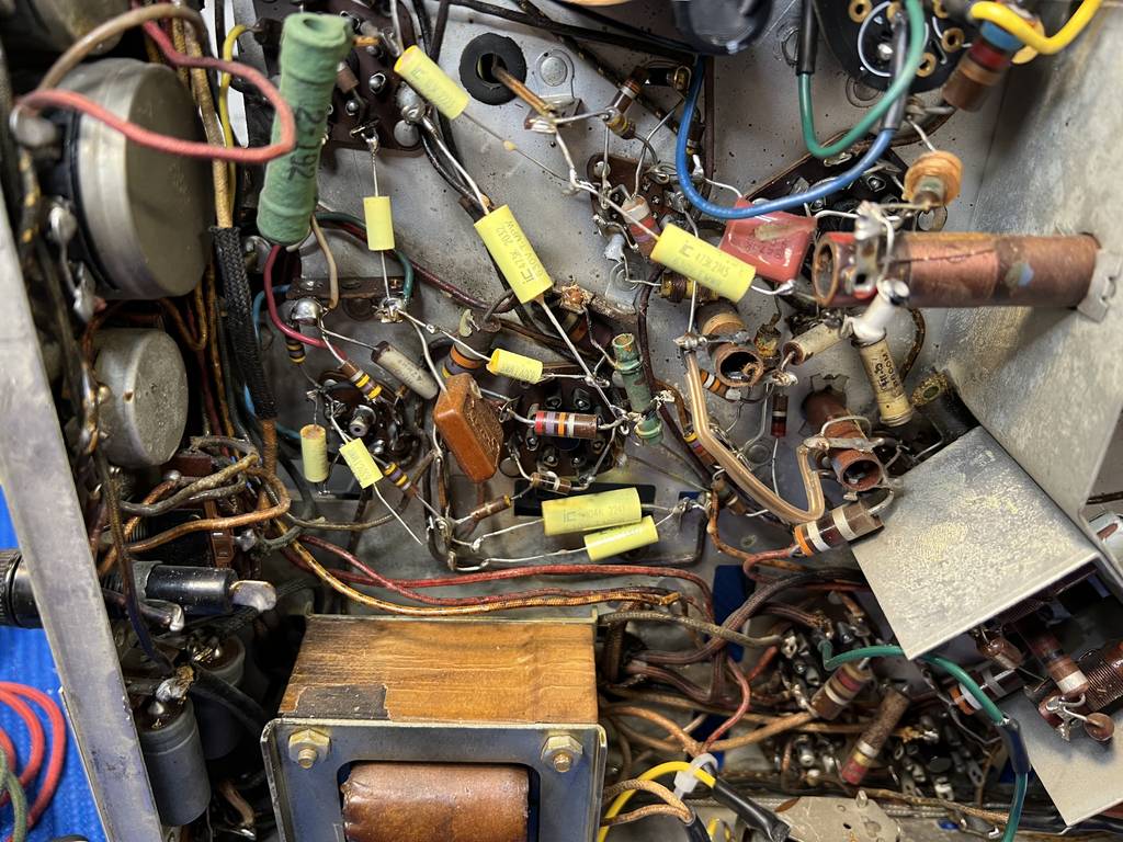  Relocation of the focus pot, not yet wired up. Should I use Tom's suggestion of a shaft extender  I'll move it back to the original position. I'll move it back to the original position.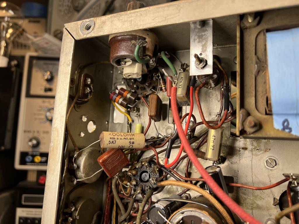 The original focus pot still in place but out of circuit. The 750ohm resistor hanging off the chassis is something I put in circuit to test TV function in the absence of a working 1K focus rheostat. It's no longer in circuit. 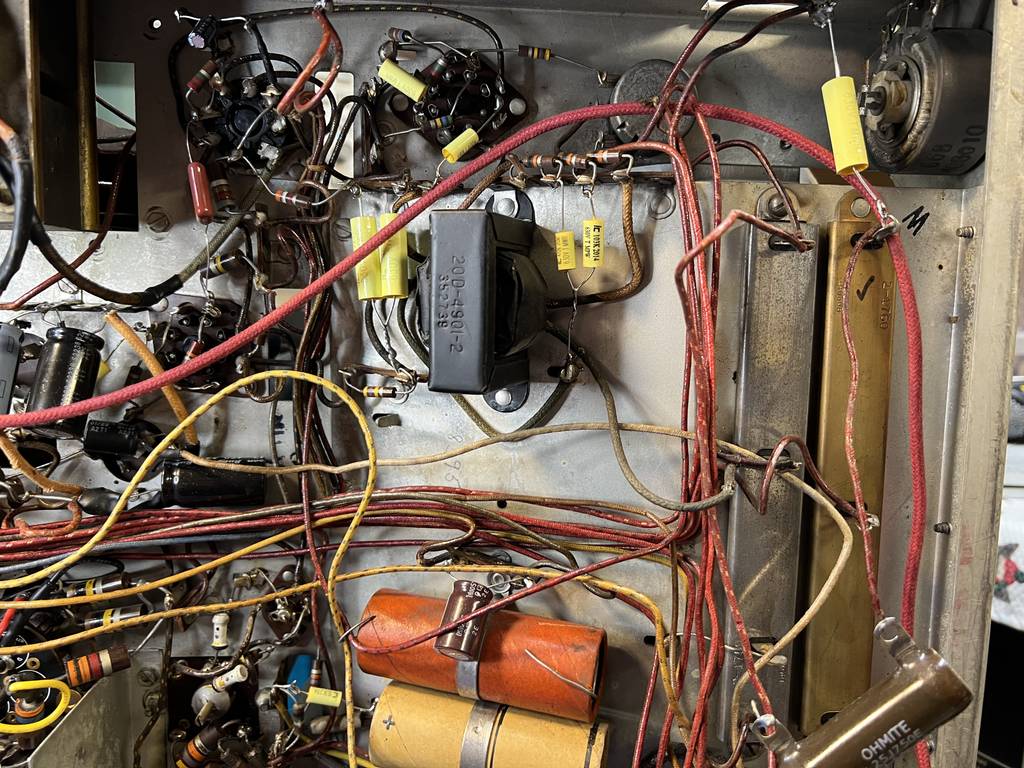 More of the chassis  Area under the HV cage  OK...so, when the relay kicks in, I have a dead short...somewhere. I'm certainly not asking anyone to review these photos and tell me where it is. I'd just like some guidance on where to start methodically running it down. My first thought was to go through my replacements one by one checking for accuracy but IDK if that's the best way. If desired, I can post photos and details of any area on the chassis and describe what's going on. Any and all advice is greatly appreciated!!!! Sorry if my ranting about criticisms offended anyone. I'm embarrassed by some of the dumb things I do! The Top Dogs here have always been kind, encouraging, helpful and reassuring. This post is not as comprehensive as I would have liked it to be but I wanted to get something out there to get started. Cheers!
|
|
#5
03-30-2024, 01:02 PM
|
||||
|
||||
|
A good way to run down a hard short is ohming out the main B+ line. If you can detect the short with a DMM unhook all branches from the main line and recheck the main. If the main isn't shorted check the unhooked branches. If one branch has a short leave it unhooked (you can reconnect the others) and disconnect what branches from it and check those. Rinse and repeat till you find it or narrow it down to a few parts and wires and check those.
In one of your photos a red and green wire meet in the foreground and don't appear to be soldered... might want to do that.
__________________
Tom C. Zenith: The quality stays in EVEN after the name falls off! What I want. --> http://www.videokarma.org/showpost.p...62&postcount=4
|
| Audiokarma |
|
#7
03-30-2024, 04:58 PM
|
||||
|
||||
|
The first place I would start is the candohm resistors. They have a nasty habit of shorting to chassis. If you replace the candohm resistors be sure to unhook all the wire connections to the terminals on the candohms. You cannot use the terminals as tie points for your new resistors. If they are not shorted now they may become so in the future.
Measure all the terminals of the candohms to chassis and see if that is where your short is then disconnect the wire and measure again if it is the candohm or the connections that are shorted. If it is not the candohm then follow the wires and the short to where it goes, disconnecting things as Tom has mentioned until you find it. Use your eyes and check for errant solder blobs and wires that may be touching.
__________________
Tim
|
|
#8
03-30-2024, 05:42 PM
|
|||
|
|||
|
Great. I will try that this evening. Not to dismiss Tom’s suggestion but disconnecting B+ leads in bulk sounds too daunting for me right now. Both original resistor cans are in circuit and in use. I’ll take a comprehensive look and document it then post.
|
|
#9
03-30-2024, 06:38 PM
|
||||
|
||||
|
Quote:
__________________
Tom C. Zenith: The quality stays in EVEN after the name falls off! What I want. --> http://www.videokarma.org/showpost.p...62&postcount=4
|
|
#10
03-30-2024, 07:57 PM
|
|||
|
|||
|
Yeah it's a spider web, a mouse trap and hedge maze held together with hundreds of 1948 style zip ties...these annoying wax covered string knots. I had a thought. The main distribution switch for the B+ appears to be the selector switch on the front for phono, FM Tel and Tel without pilot light (why?). Do you think it would be helpful to power it up with phono selected and see if it shorts when the relay closes? Do the same perhaps with the FM position selected? Could this approach eliminate some sections as the source of the problem?
I relocated the new focus rheostat in the original position and hooked it up. I don't need new problems that I might make from running new wires etc... The original canned resistors seem to be OK. The only terminal that has continuity with the chassis is the one that is connected to ground.
|
| Audiokarma |
|
#12
03-31-2024, 11:34 AM
|
|||
|
|||
|
Ditto on a Candohm resistor shorting to the chassis.
OT: I restored a 16" Admiral set, 26R12 and all was well. Reading many threads on the Antique Radio Site, there was much mention about Candohm resistors shorting to the metal casing. Many radios used them. The set was unused for a while and I wanted to watch a movie. When I turned on the set, I was greeted with quite a light show inside of the 5U4G (Admiral Labeled!) It burned open the filament of the tube rendering it useless of course. Fast forward, the Candohm was in fact shorted internally and shorted the B+ to Ground. I replaced it with a terminal strip and a ceramic resistor. (Note: this is a picture before I restored the set)
|
|
#13
03-31-2024, 12:31 PM
|
|||
|
|||
|
Well, maybe not so fast on my dismissal of the Candohm resistors. I tried it on the phono setting and it didn't dead short however, R285, the 1.28K resistor began to smoke and got blazing hot. That's the Candohm right off the choke with 435V DC on it. It didn't test as shorted to the chassis when I tested it for continuity but something major is going on there.
|
|
#14
03-31-2024, 01:14 PM
|
|||
|
|||
|
I isolated R285 and tested it to ground and for resistance. It tests perfect. I am going to replace all of these CO resistors at some point but while I'm troubleshooting, I'm not going to complicate things. I have my suspicions the issue is in how I hooked up the relay. I'm going to start with the lead that feeds the articulating top contact. As it sits, the relay closes when the 6AL5 tells it to do so. The issue is after that happens.
|
|
#15
03-31-2024, 01:44 PM
|
|||
|
|||
|
So this is the area of interest...again!
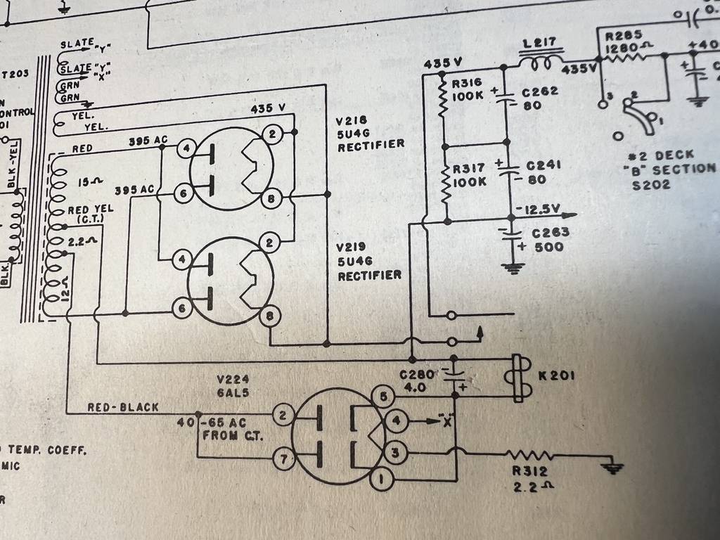 Here are the relay details. 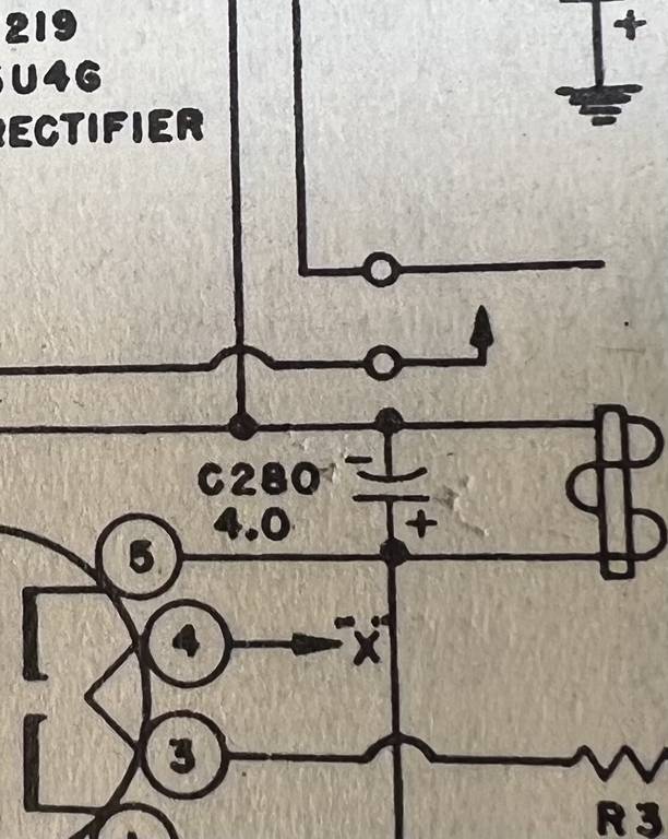 I thought the purpose of this was to give the 2 5U4 rectifiers time before they are connected to the rest of the TV but this schematic confuses me a bit. The rectifier circuit feeds into the relay at the point indicated by the bottom open circle and the arrow indicates that is the articulating contact in the relay switch correct? The top open circle is everything else and is the stationary contact?
|
| Audiokarma |
 |
|
|


 Linear Mode

