
|
|
|
#31
 02-13-2013, 11:31 AM
|
||||
|
||||
|
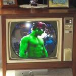
To add to the opinions above, you have the best TV ever built. The Zenith 25DC56/57 was one of the last 100% Chicago-built Zeniths, and also one of the last hand-wired by the hands of the women of the Rosie-the-Riveter era.
The FIRST thing that comes to mind, (although this would have to assume that you do indeed have high voltage and you believe you don't), is the Chromatic switch. It's a nightmare when it's dirty, and causes blacked out screen, flickering, color problems, etc. Just to rule that out, maybe turn the set on, and fiddle with the Chromatic button and see if you get anything. If not, then your first thought is probably right; no HV. If you lost high voltage, it's very easy to troubleshoot, and most everything is available for that set (either new or from other AKers). If that one has a circuit breaker, and it's tripped, you likely have either a bad tripler, or possibly a shorted horizontal output (or both). Remove the 2 screws from the horizontal output (thus disconnecting the collector), and reset the breaker (or change the chemical fuse), and then see if the 130 volt line is live. I think you can find the 130v on the case of the regulator transistor mounted next to the flyback (see the diagram in the cabinet). If the 130 volts is back, then remove the horizontal output and measure it from collector to base and collector to emitter, and see if any direction is short. If so, you likely just have a failed transistor 121-831 (or NTE 165). If the transistor isn't shorted, put it back, and on the tripler, carefully peel off the rubber glob and unsolder the wire coming from the flyback and place the wire safely away from ground, and see if the set turns on, and you should hear a corona hiss from that loose wire. If yes, you have a bad tripler. At that point, I'd update the tripler to an NTE526A, which eliminates the focus divider and double anode wire. Charles
__________________
Collecting & restoring TVs in Los Angeles since age 10 Last edited by kx250rider; 02-13-2013 at 11:49 AM. 
|
|
#32
02-13-2013, 09:37 PM
|
||||
|
||||
|
Post a want ad in the classifieds here with the Sams number & chassis. It might get more views that way. I would be surprised if somebody on here didn't have a copy to send you. It could be scanned but that's a pretty big package. I checked my factory service manuals but didn't have it. If you really can't find the Sams I'll lend you mine, I'm trying to keep my "master" set complete.
__________________
Bryan
|
|
#33
02-14-2013, 12:09 AM
|
||||
|
||||
|
Quote:
Quote:
Quote:
Quote:
|
|
#34
02-14-2013, 07:34 AM
|
||||
|
||||
|
very easy to diagnose.perhaps you can call one of us and we can walk you through some preliminary steps to help you.kx250rider s instructions were awesome in his post.doesnt get any simpler and precise as that.of course,you can always send the set to me!
|
|
#35
02-14-2013, 08:07 AM
|
|||
|
|||
|
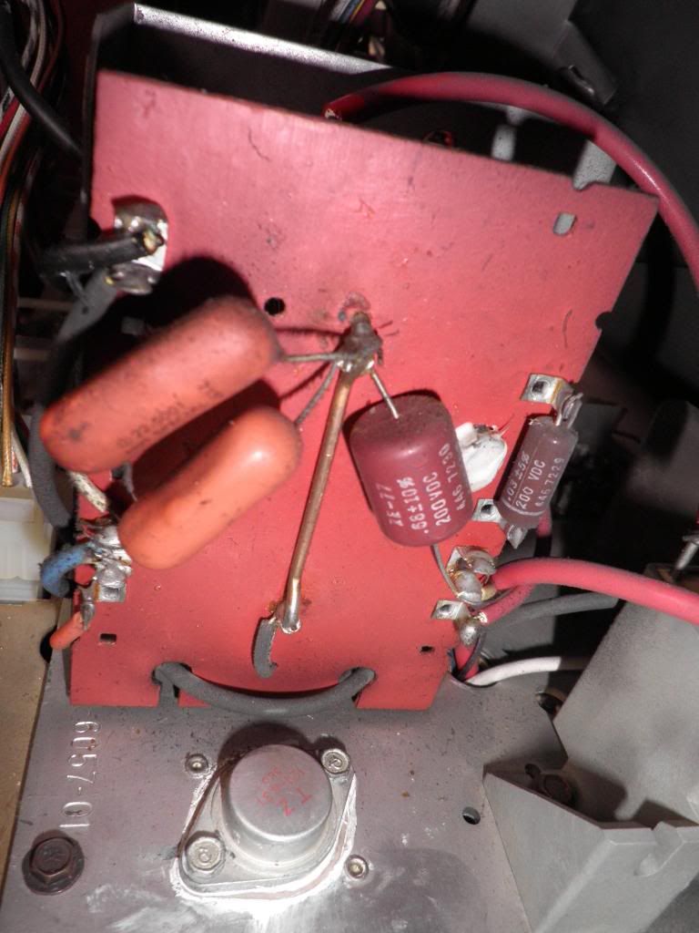
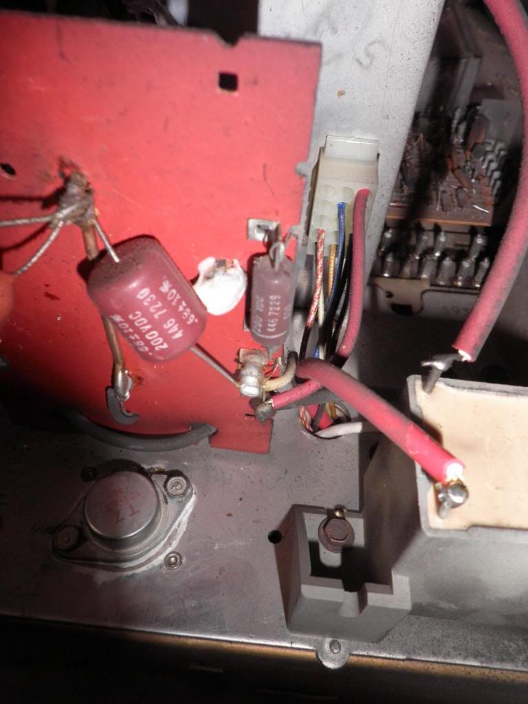
Also, be on the lookout for those early white Zenith safety capacitors.
I think in that unit, 4 or 5 are used in parallel. Zenith PN 22-5001, .0018mf @ 1.6KV. One or two would open(replace all of them) and run havoc in the Horiz. out and HV stages. Later, Zenith used one cap.(800-860) instead of paralleling .
|
| Audiokarma |
|
#36
02-14-2013, 11:45 AM
|
||||
|
||||
|
Glad to help, if I can...
I have the schematic for that set, but not at hand. The paper tag on the inside of the cabinet shows the main transistor locations, but as you point out, it's best to look over the schematic so you have a good idea what you're looking at in the set. The circuit breaker will make a "click" that you can feel when you press it if is tripped open, but if it wasn't tripped, it will just smoothly press in and spring out again with no click. If it's tripped, it's almost definitely due to a fault in the set, so to reset it may or may not cause further problems if the fault isn't found first. Honestly I might try it once, but if for instance the tripler is shorted, it could take out the horizontal output on the second zap, etc. The horizontal output is a large T03 case transistor located near the back of the chassis near the flyback (from behind the TV, toward the corner close to you on the right). The regulator is on the upright aluminum plate just to the left of the flyback. I'd at least pull out the horizontal output and measure it on the diode scale of a DMM (or on the 10K scale if no diode scale), and be sure it doesn't have a short from collector (case) to either emitter or base. No direction should read less than 1.5K, if I recall. I think there is a damper diode built into that transistor, so it will read funny as compared to a regular NPN or PNP, but no shorts. I'll see if I can dig up the schematic and post a photo, if I get a chance asap, but today/tonight are out due to Valentine's Day plans  Charles Quote:
Quote:
__________________
Collecting & restoring TVs in Los Angeles since age 10 Last edited by kx250rider; 02-14-2013 at 11:50 AM.
|
|
#37
02-15-2013, 02:57 AM
|
|||
|
|||
|
Charles,
Due to the genorosity, I now have the schematic and chassis layout pages to look at and get started. Thanks for the offer to look and post. Hope I got to you before you went nuts trying to dig it out. Will I be flipping the set on it's side or top to remove the bottom metal cover plate allowing access to the underside of the chassis for desoldering, etc? I won't have to remove the chassis itself from the set to perform any testing, is that correct? Also, do I have to fear getting zapped by stored cap charges anywhere in the set when working on it in the coming days or weeks (when in unplugged mode, of course)? We have to be very careful when working on guitar amps as the caps often hold very high voltage charges for quite some time after unplugging and must be drained first. Not aware if the tv has the same caveats. I'd hate for the membership to wonder what that glow was off in the distance in the coming days! Not the way I'd like to start the testing process. Thanks.
|
|
#38
02-15-2013, 03:02 AM
|
|||
|
|||
|
Quote:
|
|
#39
02-15-2013, 03:10 AM
|
|||
|
|||
|
Quote:
 
|
|
#40
02-15-2013, 08:00 PM
|
||||
|
||||
|
i agree with stratlou!
|
| Audiokarma |
|
#41
02-17-2013, 12:48 AM
|
|||
|
|||
|
Quote:
    Thanks.
|
|
#42
02-17-2013, 01:24 AM
|
||||
|
||||
|
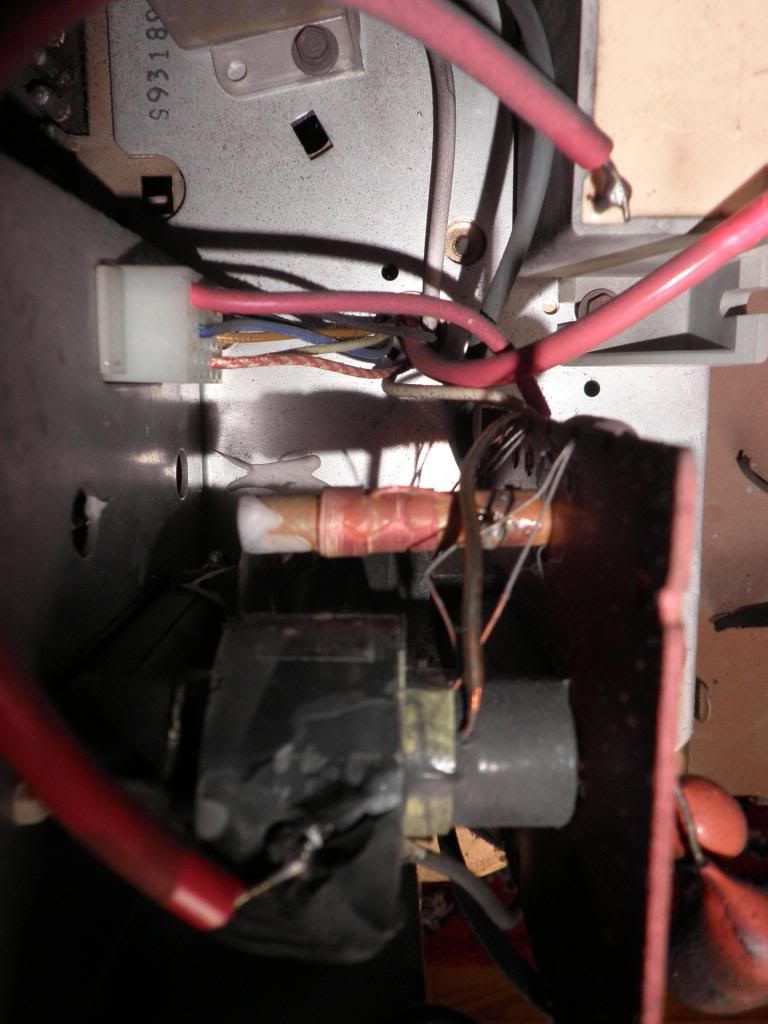
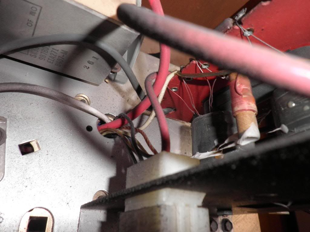
It looks like something's wrong with the Flyback, possibly burnt?
It looks like that red lead has been recently exposed at the end where it should be embedded in the tire.
|
|
#43
02-17-2013, 06:56 AM
|
|||
|
|||
|
Quote:
|
|
#44
02-17-2013, 10:12 AM
|
|||
|
|||
|
those safety caps look correct (replacements for the ones known to go bad, there should be a sticker somewhere on the back of the cabinet documenting the fix).
if you look carefully you should see the word "special" along with the part number.
|
|
#45
02-17-2013, 11:55 AM
|
||||
|
||||
|
Quote:
I think that flyback has an eye terminal on the windings; not embedded. Charles
__________________
Collecting & restoring TVs in Los Angeles since age 10
|
| Audiokarma |
 |
| Thread Tools | |
| Display Modes | |
|
|


 Linear Mode

