
|
|
|
#16
 05-30-2011, 11:47 AM
|
||||
|
||||
|
Good idea. I do have a Sencore CR70 with universal adapter. It may be possible to test the CRT by clipping to the wire stubs.
Phil Nelson 
|
|
#17
05-30-2011, 01:22 PM
|
||||
|
||||
|
I like that set A LOT!!!!!!!!!!! And I've never seen a stand-alone console 10" TV branded Capehart; only seen those in the Farnsworth brand. The Capehart name was on the big 7-foot-tall 500 series console with 10" TV, phono & hi-fi radio, but that was a different chassis altogether. That actually looks like a DuMont type cabinet, but definitely a Farnsworth chassis. I'm not sure when Capehart started making their own TV chassis, or if they were always part of Farnsworth? I know that I've seen Farnsworth radios which are not even vaguely related to the Caphehart hi-fi sets of the same years in the late 30s and early postwar; such as the 24-tube and 28-tube 400 series with the flip-over changer.
Charles
__________________
Collecting & restoring TVs in Los Angeles since age 10
|
|
#18
05-30-2011, 03:15 PM
|
||||
|
||||
|
Some quick pics. The horizontal AFC subchassis stands above the main chassis:
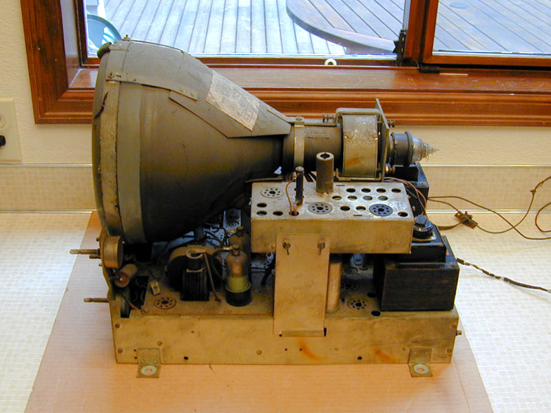 The not-well-shielded tuner is at lower right in this view: 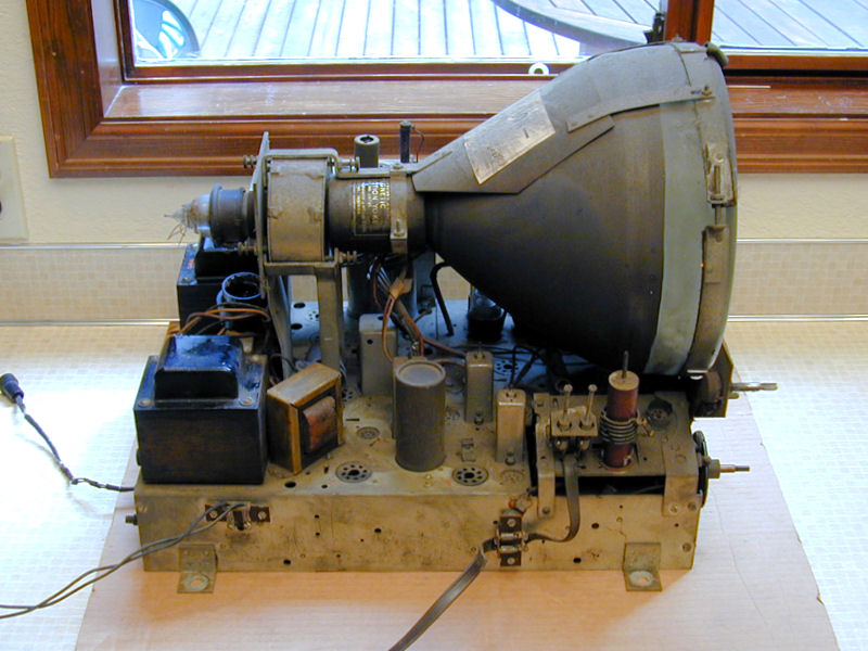 Underneath, I see a handful of replaced caps. The original small caps are the flat molded-paper type. At lower left, someone replaced a resistor between the horizontal sync and horizontal centering controls with a pair of resistors that look burned. At lower right is the HV doubler. Everything on the doubler board (resistor chains, etc.) has been painted with black insulation that looks original.  The tuner uses ganged air variable capacitors (!), similar to the General Instruments tuner in the unknown TV in my Scott 800B combo. Pilot TV-37s use a simpler tuner of that sort.  Uh-oh. One of the CRT leads snapped right at glass level. Maybe I can grind away enough glass to solder on a new lead. 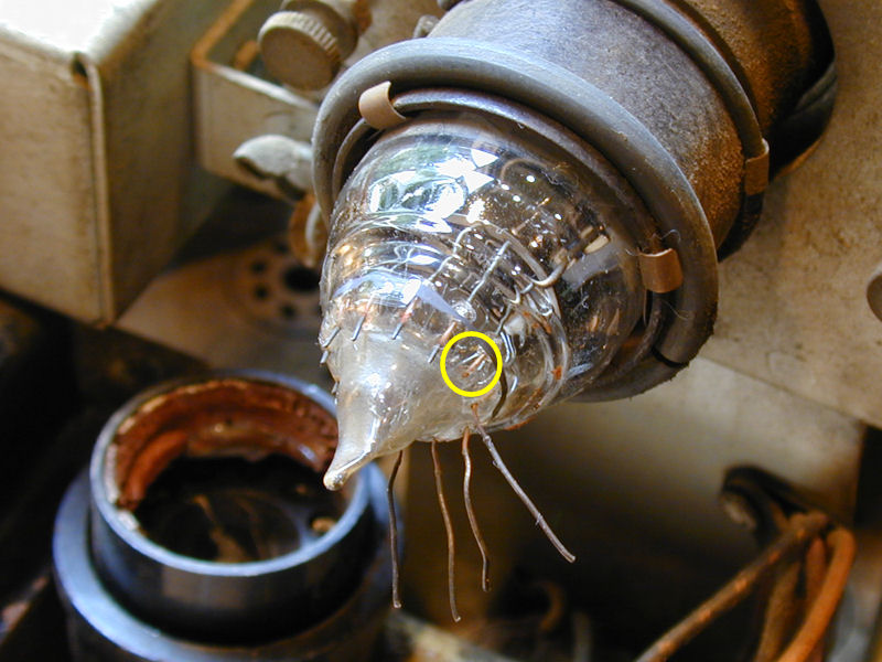 Time to gather up replacement parts. The missing tubes are common types. I should have most of them on hand. Phil Nelson
|
|
#19
05-30-2011, 03:48 PM
|
|||
|
|||
|
Phil, can you verify that that snapped-off wire is actually connected to an internal element? Vague chance it might be a 'dummy' lead or duplicated by a second lead coming off the same element? oc
|
|
#20
05-30-2011, 04:32 PM
|
||||
|
||||
|
After removing the ion trap magnet, I can see that the CRT is a 10BP4. I believe the snapped lead is on pin 10, connecting to the 2nd grid. It connects to that middle ring, anyhow. I have other 10BP4s in the house, so if this one's not salvageable, I can borrow one to get through this restoration.
Phil Nelson 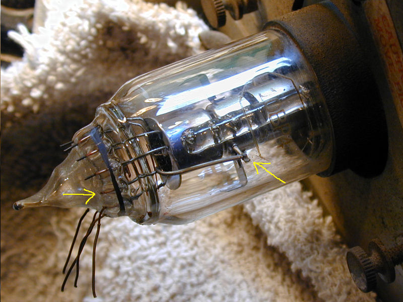
|
| Audiokarma |
|
#21
05-30-2011, 05:17 PM
|
||||
|
||||
|
Quote:
I don't think there are too many floor-standing 10-inch TV-only sets. The several Admirals (30A15 and others) are the only ones that come to mind. That was a great find, Phil!
__________________
Chris Quote from another forum: "(Antique TV collecting) always seemed to me to be a fringe hobby that only weirdos did."
|
|
#22
05-30-2011, 05:18 PM
|
||||
|
||||
|
Yee-hah! The CRT tests strong when I hold a connection to that broken lead. Definitely worth trying to salvage.
Phil Nelson 
|
|
#23
05-30-2011, 05:31 PM
|
||||
|
||||
|
Quote:
Personally, I'd be hesitant to grind down very much of the glass, because you're working with a glass to metal bond... and glass that is under a lot of pressure to boot. I wonder if one could rig up a spring-loaded needle in the CRT base that applies light pressure to make contact with that lead (much like you did by hand with the tester)
|
|
#24
05-30-2011, 05:50 PM
|
||||
|
||||
|
Good luck with salvaging that CRT. I'd be very nervous if I had to grind away at the glass to get that broken leg a bit longer..... Nice set by the way looking foward to your restoration adventures on it!
 ...Cheers ...Cheers
__________________
Visit my Vintage TV & Radio Page - http://nzvintagetvradio.blogspot.com/ My YouTube Link - http://www.youtube.com/user/glenz1975?feature=mhsn
|
|
#25
05-30-2011, 06:12 PM
|
||||
|
||||
|
I know I have read about someone (Eric H?) who at least thought of filing or grinding out enough glass to expose a broken lead. Whether he actually tried it, much less succeeded, I don't recall offhand.
Wish I was better friends with my dentist. Bet she could do it in no time, and she's got the gear: water-cooled instruments, super magnifying goggles, etc. Phil Nelson
|
| Audiokarma |
|
#26
05-30-2011, 08:53 PM
|
|||
|
|||
|
Phil, is that lead busted off absolutely flush with the glass? If there were as much as 1/64" of a stub sticking out, it should be possible to solder to it. I would take a single strand from a lamp cord and bend it double, then hook the U-bend over the stub and solder it.. after first cleaning the stub thoroughly so it'll take solder readily. The resultant lead would consist of two strands of lamp cord wire - easily manipulable without straining the connection. oc
|
|
#27
05-30-2011, 09:08 PM
|
||||
|
||||
|
If the current draw on that pin is really low in normal use, you might get away with some form of conductive paint or epoxy.
Or solder a thin lead to the flush broken off lead area, and epoxy over it to keep it from breaking off. I'd do it while you have the CRT set up on that test setup, to be sure you really did connect.
__________________

|
|
#28
05-30-2011, 09:46 PM
|
||||
|
||||
|
There really isn't a stub at all. If anything, the wire end may be slightly recessed in the glass. It's hard to see, much less reach.
 I tried soldering single copper strands to the existing leads, just to see how hard it will be to attach guide wires. I scraped the old leads shiny and tried to tin them beforehand, but had a heck of a time getting solder to stick at all. Is there something else I can do to improve adhesion? If not, I see no chance that I could solder a strand to that stub. Maybe cleaning the stub shiny and fastening a lead with epoxy is the best I can do. I'll need to redo the test strands, in any case. They're only about an inch long. I realized too late that it'll be easier if they're several inches long, so you can bend and insert each guide wire separately, rather than try to line them up and insert all at once. Phil Nelson
|
|
#29
05-30-2011, 10:44 PM
|
||||
|
||||
|
Quote:
I believe you were thinking of my messed up 7JP4. I used a needle file to carefully expose enough of a lead to accept solder. Not something I'd want to do everyday, but it did work 
Last edited by bandersen; 05-31-2011 at 12:37 PM. Reason: replaced pictures with link
|
|
#30
05-30-2011, 11:16 PM
|
||||
|
||||
|
That must be it. Looks like that tube had a raised glass dimple around each wire, which you could file away. On this one, I'd need to dig a little crater around the wire.
Phil Nelson
|
| Audiokarma |
 |
|
|


 Linear Mode

