
|
|
|
#31
 07-02-2014, 11:45 PM
|
|||
|
|||
|
Awesome restore MIPS!
i have the original canadian service info for this set if you still need it. pm me your email and i can scan and send over the next few days. have a good one, RonL 
|
|
#32
07-04-2014, 03:08 AM
|
|||
|
|||
|
Hi Mips.
Got your pm-will scan info and try the "dropbox" site to get info to you. also, Main electronics might still have the "tire" you need for your turntable. also you asked "does anyone know which pin is CRT anode output on the 1B3GT so I can reattach the cable?" it goes to pin 7 of the 1b3 hv rectifier. ill get the scans done over the weekend cheers, RonL
|
|
#35
07-09-2014, 12:34 AM
|
|||
|
|||
|
there is nothing more satisfying than to take something that most people would consider trash and ,look at it and see what it could be in your mind, then slowly bring it back to a condition better than it was when it was new. great job
|
| Audiokarma |
|
#36
07-17-2014, 10:30 AM
|
||||
|
||||
|
Okay, so I've ran into substitution and sourcing said substitutes.
There's still three caps left in the set -475v 20uf -400v .5uf -600v .033uf I've been talking to a few friends about replacements and we agreed that no exact values could be affordably found so we looked into substituting with the following: -22uf 475v -470nf 400v -33nf 600v I can source the latter two caps here and here but I'm still having trouble with the 22uf cap. I'm also unable to source three more cheap 600v .01 orange drops. They were cheap at Main Electronics but they don't ship orders under $25 so again I'm forced to buy online where the cheapest cost so far I've found was $10 for one. :/ Unless I can figure out this cap issue the whole project is suspended until I can get back down to Vancouver. Last edited by MIPS; 07-17-2014 at 10:35 AM.
|
|
#38
09-10-2014, 05:51 AM
|
||||
|
||||
|
Woo, progress! Recap has been completed.
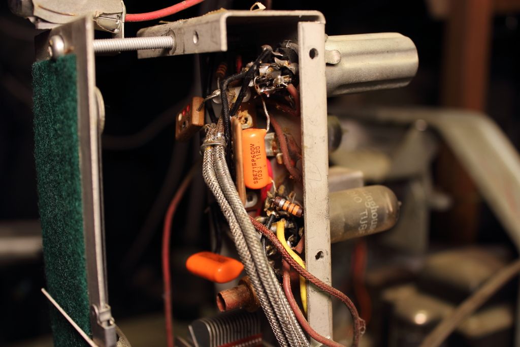 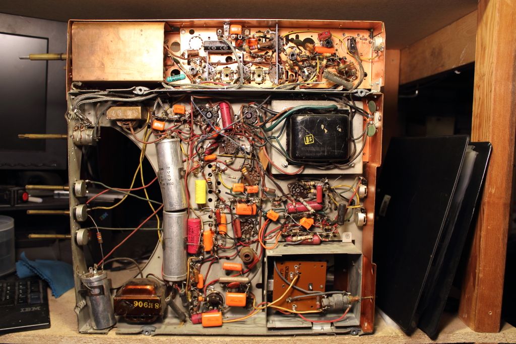 The multi-cap cans are still there but I"m not touching those until I'm positive they have problems. I don't even know where to start on figuring out how their pin arrangement works. All but two tubes have been checked on my Sencore. A number of them gave weak emissions but improved after a few minutes of cooking. I did however find a 6BE6 that had good emissions and life test but was pegged on BAD on grid leakage (once warm it crawls up and pegs, not an immediate swing-to-peg). I also have a 6W6GT but my setup chart only showed the 6W6. Are these two compatible for testing? The other tube not checked was the IB3GT which on inspection had a cloudy glass envelope near the base. Unsure if it's a manufacturing defect or sign the tube gassed. I could not get the Sencore to give any reading with it plugged in but I'm aware these tubes don't really work in most testers because of their design so if it works it works, else I have replacements for it and the 6BE6. 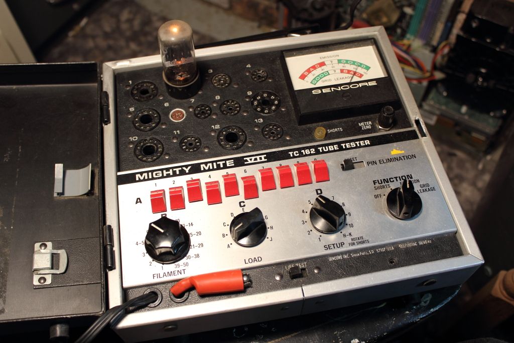 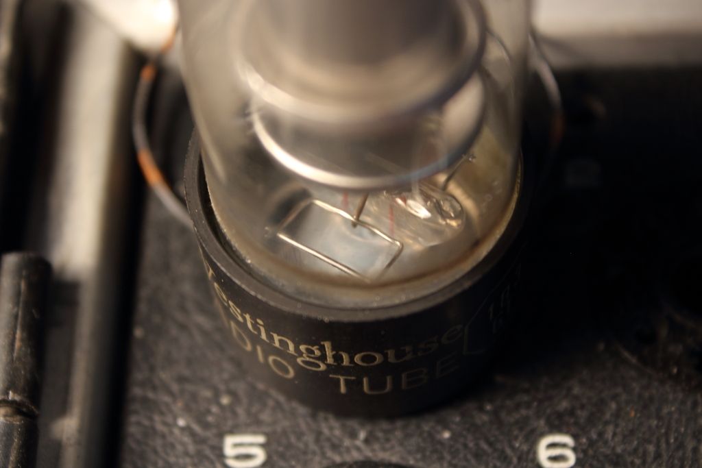 The only other thing I did tonight was reconnect the anode cable. It's pin 7 on the IB3GT but the socket is confusing because pin 7 for some wild reason also has a lead which makes the socket base and the support live with a few thousand volts. It's isolated form the chassis by a ceramic tube buy why would they of done this? 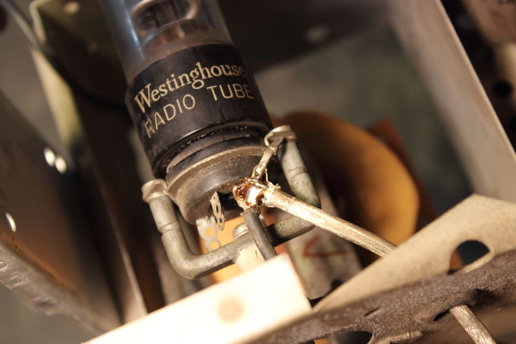 Now that everything seems good it's time to attach the variac and lightbulb and see if it wakes up gracefully. The issue however is that my variac is only rated for 1A (what an amazing chinese product) so I would rather not push it past 2A so I want to limit the current I want to keep the CRT out and kill the high voltage. Any ideas on how to quickly cut that for now? One last thing. Four of the pots on the front and rear of the chassis won't free up. I've gone at them with penetrating oil and WD 40 but only one other pot freed up. Should I dismantle and clean these old ones or replace them? Last edited by MIPS; 09-10-2014 at 06:13 AM.
|
|
#39
09-10-2014, 11:36 AM
|
||||
|
||||
|
Quote:
This article has more information about replacing can electrolytics, with links to other articles that illustrate various methods: http://antiqueradio.org/recap.htm In my experience, leaving those old electrolytics in place is not a good idea for the long term. They can fail at any time without warning, even if they seem to function now. Quote:
Phil Nelson Phil's Old Radios http://antiqueradio.org/index.html
|
|
#40
09-10-2014, 04:17 PM
|
||||
|
||||
|
My best guess for the 1B3 socket is either the ceramic tube isn't original and you were supposed to have a doorknob cap there, or the ceramic tube IS original and the metal all being at high voltage reduces corona losses...
|
| Audiokarma |
|
#41
09-10-2014, 07:23 PM
|
||||
|
||||
|
From what I can see the gether on the 1B3 has turned white a sure sign the tube has lost it's vacuum and is dead, I'd replace it if I were you.
I see at least 6 red and one green plastic molded tubular paper capacitors those NEED to be REPLACED they are every bit as bad as the wax and cardboard shell type paper capacitors IF NOT WORSE. Back in the day the same chassis was often offered in a plethora of cabinet models with a variety of CRT sizes/types depending on cabinet...If one or more of the CRTs it was used with was a metal cone type then there would have been a HV door-knob style capacitor in place of that piece of ceramic, and it may have been easier/cheaper on the all glass CRT models (if that chassis served both types) to simply leave out the expensive unnecessary cap and toss that ceramic insulator in...Rather than drastically change the HV rectifier mounting in the glass CRT model....It could also be a hold-over from an older chassis that did drive metal cone CRTs
__________________
Tom C. Zenith: The quality stays in EVEN after the name falls off! What I want. --> http://www.videokarma.org/showpost.p...62&postcount=4
|
|
#42
09-10-2014, 07:42 PM
|
||||
|
||||
|
Quote:
|
|
#43
09-10-2014, 07:50 PM
|
||||
|
||||
|
Yup! I calls 'em as I sees 'em.
A controlled start with a variac would not be out of the question though as a majority of the weak points are gone, and you could get lucky on the rest. In my experience BTW one can run variacs and isolation transformers well beyond their current ratings for a short time without any illeffects...Over heating is their failure mode and if the overload is not too extreme it can take north of 10 minutes for that to happen...Plenty of time for warmup and some futzing around.
__________________
Tom C. Zenith: The quality stays in EVEN after the name falls off! What I want. --> http://www.videokarma.org/showpost.p...62&postcount=4
|
|
#44
09-10-2014, 08:21 PM
|
||||
|
||||
|
Quote:
http://antiqueradio.org/recap.htm Those pink "Big Chiefs" are on the must-kill list, along with striped "bumblebees," flat "Micamolds," and wax paper. Phil Nelson
|
|
#45
09-10-2014, 09:37 PM
|
||||
|
||||
|
Wow, that contradicts the last page I saw on identifying goods and duds.
I'm pretty much beat but I'll try bringing the rig up tomorrow. Any ideas yet on killing HV for now or will removing the gassy IB3GT suffice?
|
| Audiokarma |
 |
|
|


 Linear Mode

