
|
|
|
|
|
#1
 07-16-2015, 10:25 PM
|
||||
|
||||
|
Miller 6195 -- thanks for the tip. PTOP is the outfit that has 4.5-MHz traps in stock. They also have the Miller 6195 coil and they suggested another that might work, so I ordered them both.
Phil Nelson 
|
|
#2
07-17-2015, 09:40 PM
|
||||
|
||||
|
Quote:
__________________
Tom C. Zenith: The quality stays in EVEN after the name falls off! What I want. --> http://www.videokarma.org/showpost.p...62&postcount=4
|
|
#3
07-19-2015, 12:47 PM
|
||||
|
||||
|
Quote:
Phil Nelson
|
|
#4
07-20-2015, 11:02 PM
|
||||
|
||||
|
Okay, here are the key video preamp parts. From left to right, we have three Miller TV-151 4.5-MHz sound traps, a Miller 6195, and a Miller 4566:
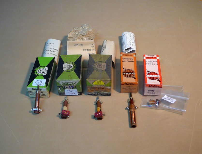 There are minor differences among the three TV-151s, but presumably they work the same. The last two are adjustable across the target value of 400 muh given for L3 in the schematic; I'm hoping that one or the other will work. Tomorrow I'll gather the other components and start building. Phil Nelson Phil's Old Radios http://antiqueradio.org/index.html
|
|
#5
07-28-2015, 11:57 AM
|
||||
|
||||
|
Quote:
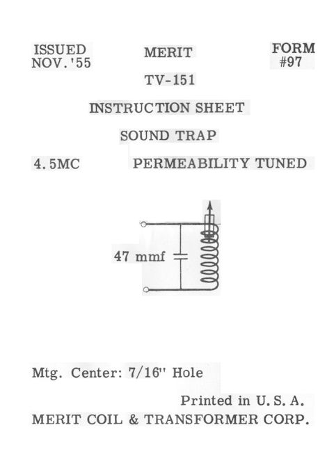 The sheet identifies that as a 47-mmf cap. Two of my traps have a 47-mmf cap and the third has a 45-mmf cap. They all measure 2.2 ohms across the coil: 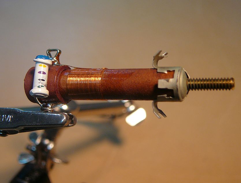 I put one of them on a scope with a 4.5-MHz signal and was able to peak the amplitude by turning the adjuster. I don't know if that's where you want the adjustment to be in the preamp, but I was curious. 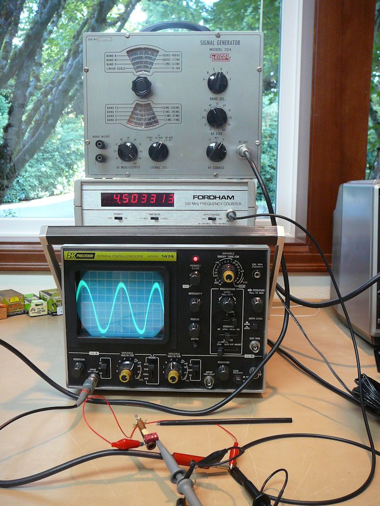 Haven't done much beyond that inspection, except to collect the needed parts. Perhaps I will create a new thread about building the preamp. Phil Nelson Phil's Old Radios http://antiqueradio.org/index.html Last edited by Phil Nelson; 07-28-2015 at 12:15 PM.
|
| Audiokarma |
|
#6
08-08-2015, 01:04 PM
|
||||
|
||||
|
Back to the video preamp plan, with a question about the heater connection. I posted the original article at:
http://antiqueradio.org/art/RCA_Broa...eo_Preamps.pdf The plan I'd like to build is on the last page of the article, which says, "The heater connection is made to pin 4 of the adaptor socket." The heater connection is to service the 12AT7 tube on the preamp. Here's the 12AT7 basing diagram, showing that its heater is center-tapped at pin 9. 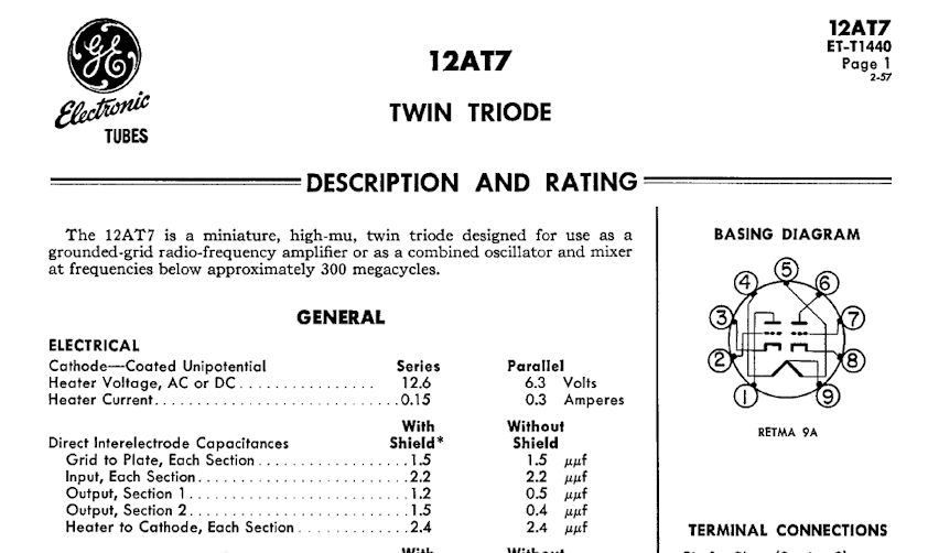 The article tells you to connect the heater connection to pin 4 of the adaptor socket. That's clear, but I want to make sure I understand the way they drew the heater connections in the preamp schematic: 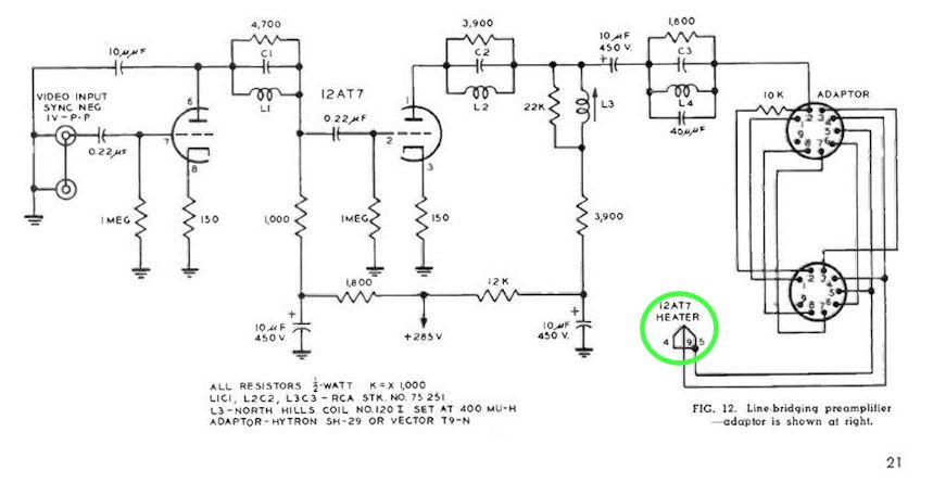 The drawing seems to show pin 4 of the adaptor connecting to pin 9 (the center tap) of the 12AT7. And pin 5 appears to be jumpered to pin 4. Or am I reading the schematic incorrectly? (The ground connection for the heater is made through pin 5 of the 6CL6 1st video amp tube, whose socket the adaptor plugs into.) Phil Nelson
|
|
#7
08-08-2015, 03:33 PM
|
||||
|
||||
|
Quote:
What could be missing on the schematic is the connection from ground of the TV to the ground of the added preamp... IMHO, the wire from pin 5 of the 6CL6 socket should also be connected to ground(s) of the preamp. jr
|
|
#8
08-08-2015, 08:56 PM
|
|||
|
|||
|
Yup, the whole family of 12V twin triodes (12AT7, 'AU7 'AX7, 'AY7, 'AZ7 etc) have the centertap for 6V heater operation.
|
 |
|
|


 Hybrid Mode
