
|
|
|
#1
 03-29-2012, 05:30 PM
|
|||
|
|||
|
Is this a good design for a one tube regen?
First of all id like to say thank you to everyone whos helped me this last year, ive learned a ton. I think ive picked up more by reading various posts than from the rather dry electronics books ive read.
Ive decided to try and build a simple one tube regenerative radio. Id like to know if this is a good schematic for one. Ive seen several variations and frankly i dont know if one is better than another.  also i picked up this modified atwater kent condenser, am i able to use it for this? If i get this working then id love to build a nice breadboard style chassis for it. Ive a piece of coca bola wood ive been dying to use for something.  
__________________
"Good morning whiskey, good morning night. The end of the world is in my sight." Hank 3 
|
|
#3
03-29-2012, 09:34 PM
|
|||
|
|||
|
Is there anything you would change?
Also the atwater kent condenser, is it useable in any part of this application? Or just something i should stick on the shelf to look neat?
__________________
"Good morning whiskey, good morning night. The end of the world is in my sight." Hank 3 Last edited by jbivy; 03-30-2012 at 07:35 PM.
|
|
#4
03-30-2012, 01:03 AM
|
|||
|
|||
|
Well there is a problem in that there is no control over regeneration. I'd put a variable resistor across the feedback coil; when the resistance is zero there will be no feedback and when the resistor is high you can get as much feedback as you like. Maybe a 10k or 50k pot there.
I don't know anything about the capacitor. If it suits the circuit, you can use it. You can probably figure out how much inductance to wind to resonate with it across the broadcast band.
|
|
#5
03-30-2012, 07:47 AM
|
||||
|
||||
|
Quote:
inductor with the antenna coil can be varied to control regeneration. Regards.
|
| Audiokarma |
|
#6
03-30-2012, 09:23 AM
|
|||
|
|||
|
Lacking a physical adjustment of the tickler ('rotor') coil to throttle regeneration, you'd definitely need a control across it. I've used a 50K pot in that application (with the shell grounded to minimize capacitive effects when using it). Other people have used a small variable cap there instead of a pot.
|
|
#7
03-30-2012, 02:03 PM
|
||||
|
||||
|
Dave Schmarder's schematic uses a variometer so requires having that instrument which you don't. The plug in coils you show in your picture appear to be a broadcast coil and then the next one higher. I used to have a set of those, ICA brand, many years ago, and they look like they were intended to be used with a 140 mmfd. variable cap, which was often used in short wave regenerative receivers. Those coils usually have a label on top indicating their use. The A-K condenser you show probably has a higher capacity and may be 365 mmfd. So far none of this is working out, is it? But stay tuned! Look around for some other regen schematics that give you specs on winding the coil(s) (best to make one for the broadcast band first to get used to it) and that have a regeneration control that is more common: they will typically be either a 50,000 ohm pot or a variable cap. No. 30 tubes are getting expensive but you can use a lot of different tubes for a regen. You might have some tube on hand that would serve. Using a triode would be good for a first regen; some more advanced designs use screen grid or pentodes for smoother control. Things to consider are heater/filament voltage, do you have a supply for same. Regens often work better off batteries: some can have hum problems off of AC. The B+ supply can be several 9 volt batteries snapped together, and the A supply can be D cells on a 1 or 3 volt tube.
__________________
Reece Perfection is hard to reach with a screwdriver.
|
|
#8
03-31-2012, 02:56 PM
|
|||
|
|||
|
Well.. this has been a lot to think about. The price of the type 30 tube doesnt phase me, 15 bucks one way or the other isnt bad.
Id like to use this A-K piece in something though. Is there a design, a type, you think i should try and build as my first tube radio build?
__________________
"Good morning whiskey, good morning night. The end of the world is in my sight." Hank 3
|
|
#10
03-31-2012, 07:18 PM
|
|||
|
|||
|
Well its variable and says 0-100 on the dial and an "8-40" scratched onto the bakelite. As for the plug in coils..ive zero clue as to what theyre setup for.
__________________
"Good morning whiskey, good morning night. The end of the world is in my sight." Hank 3
|
| Audiokarma |
|
#11
03-31-2012, 10:56 PM
|
|||
|
|||
|
Perhaps the variable capacitors are adjustable from 8 to 40 pF but that's a long shot. The plug in coils either need to be reverse engineered as to turns and wire size etc. or measured. Or simply scrapped and the forms re-used.
Here is a situation where an impedance bridge would be very useful. Barring that, you can connect the variable capacitor to a coil and measure the resonant frequency. No stock answers here, sorry.
|
|
#13
04-01-2012, 06:35 AM
|
||||
|
||||
|
Is there a model number on the A-K condenser? I suspect it's for the broadcast band. I would open it up and determine just what is inside and where the connections go to the outside. Do we know it's a condenser and not a variometer? There's that tube socket on the back which doesn't look standard and looks removeable.
Here's an experiment: use test jumpers and haywire up a crystal set with the condenser and the long winding of each coil. All you need is the jumpers, a germanium diode, and some high impedance headphones. If you don't have the latter, you can use a powered computer speaker with its built-in amp. Best with an outdoor long wire but if you don't have that string out 20 feet or more of wire wherever you can. This might just tune the broadcast band. If you pick up a station, listen for its frequency and note how far open the condenser plates are, and compare with an operating radio tuned to that station. If they are about the same angle then you're in business. Edit: adding the schematics below. First one is with headphones. Second is if you are using an external amp like a computer speaker/amp. R can be anything from 10K to 50K ohms, higher the better, C can be from .01 to .047 mfd. H goes to the high side of the amp input (center conductor on a shielded cable) and S goes to the shield side. Turn up the volume on the amp. Notice that the set uses a direct ground connection so don't do this with an AC/DC amp unless you use an isolation transformer. A computer speaker/amp will be OK. In both cases ignore that the antenna is tapped on the coil and connect the antenna to the top of the coil along with the stator of the condenser and the anode of the crystal. The cathode of the crystal goes towards the right and is the band painted on the crystal, although it will work whichever way around you install it. Do you have a signal generator? Could also use that loosely coupled to the coil and sweep all over the place searching for the resonant frequency range. 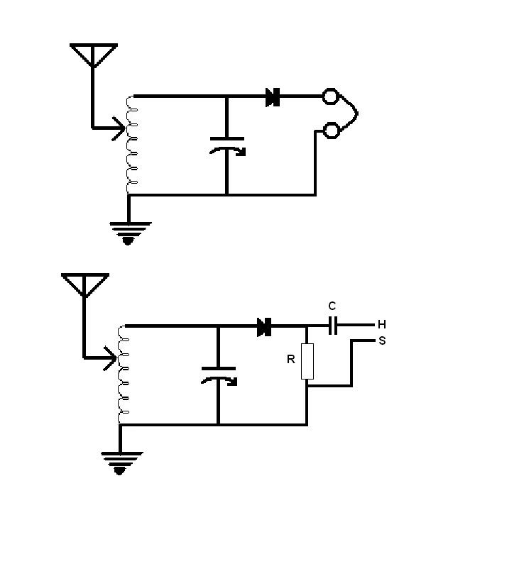
__________________
Reece Perfection is hard to reach with a screwdriver. Last edited by Reece; 04-01-2012 at 09:21 AM.
|
|
#14
04-01-2012, 01:06 PM
|
||||
|
||||
|
this website will help you figure out what those coils are
http://midnightscience.com/formulas-calculators.html I made a coil for a regen using the single layer solonoid calculator for the antenna coil, and then estimating the number of turns for the tickler. Project is as yet incomplete but all the coils and parts are collected. You can use a frequency generator, a scope or vtvm, and a fixed resistance to measure reactance of the coil at a specific frequency, and then reverse calculate what the inductance is. Same deal for an unknown variable capacitor. Regen control can be a resistor. Take a look at this, this guy's website inspired me to build my own regen. I am actually using a 6BF6, but a 30 will look more pretty. Read the "original text in pdf format" too. http://www.bignick.net/Morgan_Radio/Radio_1.htm
|
|
#15
04-06-2012, 06:20 PM
|
|||
|
|||
|
Well im thinking of chickening out of building my own regen. Ive found a complete but beat up radiola 18. No tubes broken dials and just the chassis. I was thinking of cleaning it up and maybe modernizing it.
Seeing a working regen in front of me may help, then learning how to design. The a&k condenser works out to be a 30-400pf , though ive yet to try out the coils on it. Dont think ill be using it untill i do build a breadboard radio.
__________________
"Good morning whiskey, good morning night. The end of the world is in my sight." Hank 3 Last edited by jbivy; 04-06-2012 at 08:49 PM.
|
| Audiokarma |
 |
|
|


 Linear Mode

