
|
|
|
#46
 10-23-2023, 03:16 PM
|
|||
|
|||
|
Quote:
The markers 42.17mc and 45.75mc are supposed to be at 50% +/- 5% down the curve and they are currently at 49%. 42.75mc and 45mc are supposed to be 85% +/- 15% and they are currently at 78%. The 47.25mc trap is just slightly off from being perfect too. I can only imagine what negative gain was doing to the chroma signal. It is impressive that the TV was able to draw a picture with how badly it was misaligned. Alignment would absolutely be impossible to achieve without the proper tools, and even with the proper tools, it takes lots of trial and error. Last edited by LukeSimon; 10-23-2023 at 03:21 PM. 
|
|
#47
10-24-2023, 12:38 AM
|
|||
|
|||
|
I readjusted the audio traps and the tilt and this is the closest that I have gotten the IF response to the Magnavox service manual. As in the Magnavox service manual, the bode plot is inverted on both X and Y axis. So frequency increases from right to left, and amplification increases from top to bottom.
Frequency: 41.65mhz (chroma lower) Target: 20% +/- 5% Actual: 17% Frequency: 42.17mhz (chroma mid) Target: 50% +/- 5% Actual: 51% Frequency: 42.75mhz (chroma upper) Target: 80% +/- 15% Actual: 81% Frequency: 45.00mhz Target: 80% +/- 15% Actual: 81% Frequency: 45.75mhz (luma mid) Target: 50% +/- 5% Actual: 51%
|
|
#48
10-26-2023, 02:23 AM
|
|||
|
|||
|
Chroma alignment was so bad in the beginning. This chroma response took me hours of tuning coils. The double slug coil was especially challenging because the two slugs were touching each other. Every marker is spot on except the gain for 3.58mhz is too low by 5%. I will touch it up after some rest.
Note the marker for the 4.5mhz trap on the far right. The Sams procedure for aligning the 4.5mhz trap is useless. It is easiest to align it when aligning the chroma bandpass. Last edited by LukeSimon; 10-26-2023 at 02:27 AM.
|
|
#50
10-30-2023, 06:04 PM
|
|||
|
|||
|
After aligning IF and RF, the color is much sharper and there is no more smearing/ bleeding of colors. However, the hue (tint) is wrong now (approximately 90 degrees out of phase), and just as before, the tint control has little effect: maybe 5 degrees phase shift up or down.
I have two hypotheses: first is that the tint control is not shifting the phase of the color oscillator the full range of plus/minus 30 degrees. I will oscope the oscillator to test that hypothesis. The second hypothesis is that the IF and/or chroma bandpass alignment is what is causing the tint control to not work. Remember, before I did this alignment, the tint control didn’t change the hue. But the alignment was very bad before too. If the alignment is not symmetric on both 0.5mhz side bands of the 3.58mhz chroma signal carrier, then during demodulation, the average of the side bands is what becomes the Pb and Pr signals. I think that reduces the effectiveness of the tint control’s range. I will test this hypothesis after ruling out tint control not phase shifting the oscillator. Last edited by LukeSimon; 10-30-2023 at 06:09 PM.
|
| Audiokarma |
|
#51
10-30-2023, 10:10 PM
|
|||
|
|||
|
Quote:
|
|
#52
10-30-2023, 10:27 PM
|
||||
|
||||
|
Quote:
__________________
=^-^= Yasashii yoru ni hitori utau uta. Asu wa kimi to utaou. Yume no tsubasa ni notte. いとおしい人のために
|
|
#53
10-30-2023, 11:30 PM
|
|||
|
|||
|
Quote:
|
|
#54
10-31-2023, 12:11 PM
|
||||
|
||||
|
Quote:
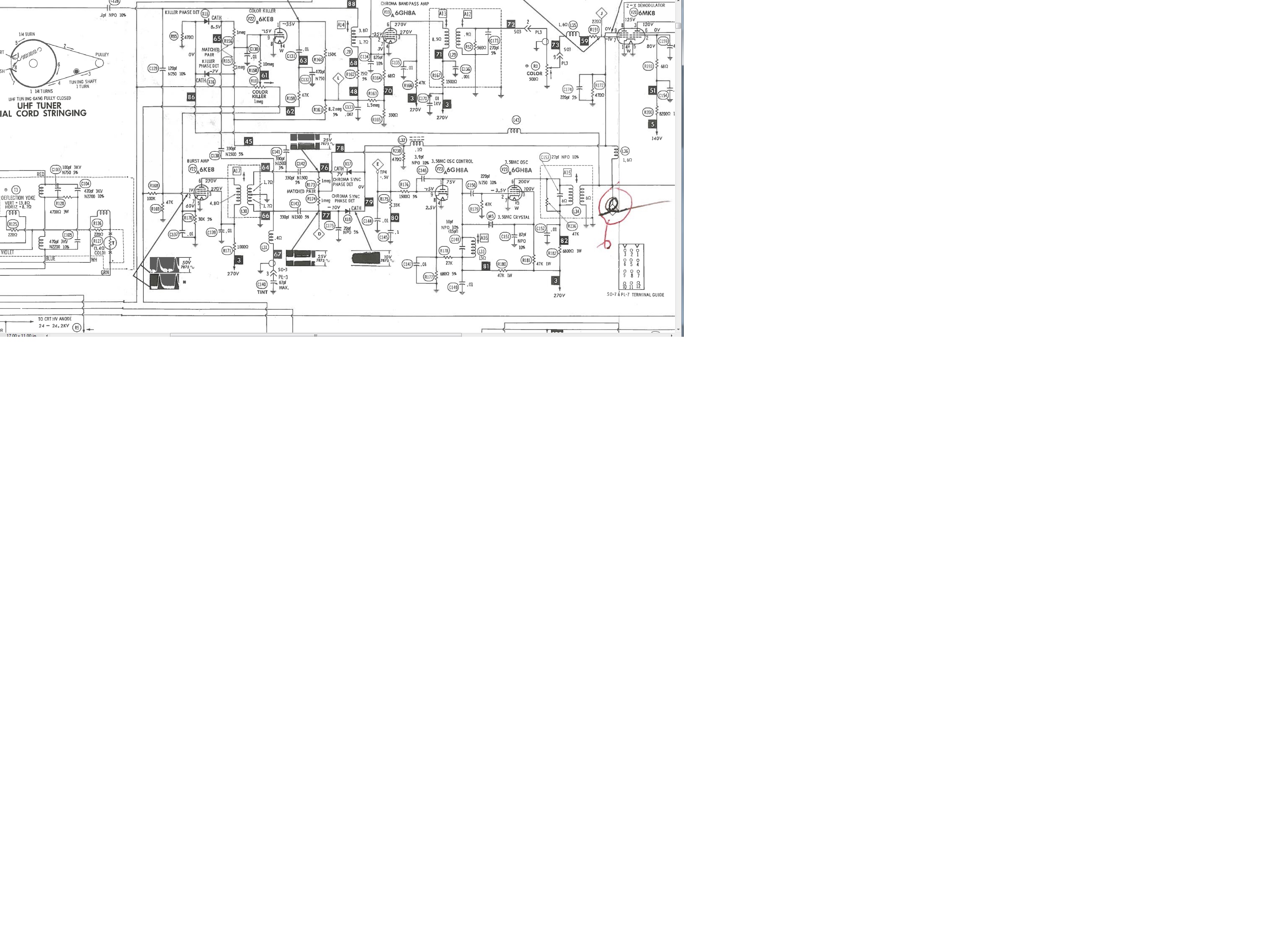
So, I think your problem likely is in the tint control area itself.
|
|
#55
10-31-2023, 12:56 PM
|
||||
|
||||
|
The way it's done in this set seems rather odd to start with, I have never seen a air capacitor (variable) used for tint before, especially on the front of a set on a long wire like this, just seems like extra trouble.
As mentioned with my set, it did not like some NOS tubes in various places, V22 being one of them, I had to try a few new 6KE8s till it worked well, loss of color (killer problem) and reduced tint range was the result when it harfed on a tube it did not like.
__________________
=^-^= Yasashii yoru ni hitori utau uta. Asu wa kimi to utaou. Yume no tsubasa ni notte. いとおしい人のために
|
| Audiokarma |
|
#56
10-31-2023, 12:57 PM
|
|||
|
|||
|
Assuming the voltages are correct on the 6KE8/burst amp, adjusting A17/L30 should be able to grab the correct tint range. Seems like, anyhow.
Edit. Forgot, some Maggies did have a 'distant' variable cap for tint. Thanks, Y'42 Last edited by old_coot88; 10-31-2023 at 01:01 PM.
|
|
#57
10-31-2023, 11:05 PM
|
|||
|
|||
|
The distant variable air capacitor does seem problematic. It is connected by a grounded cable from behind the tint dial on the front of the TV. So that grounded cable is itself a capacitor between the cable and the grounding around it. I bet the total capacitance of the grounded cable is a sizable amount of the capacitance of the variable air capacitor.
I will redo chroma AFC alignment, oscope the range of phase shift of the oscillator and then hopefully that sheds light on why tint control lacks range.
|
|
#58
11-01-2023, 01:03 AM
|
|||
|
|||
|
I am pretty sure I know what is going wrong. The Sams instructions for aligning the color AFC are easily misunderstood. It talks about adjusting the oscillator transformer for max VTVM deflection, and then adjusting the burst transformer for maximum deflection. I was interpreting that to mean maximum negative DC bias at the test point.
But I found an RCA book that explains that oscillator transformer is peaked for max negative voltage and the burst transformer is peaked for maximum voltage. The Magnavox Tabs Manual explains the theory of the phase detection circuit too, that is, the burst is supposed to be 180 degrees out of phase with the oscillator, and they are supposed to be approximately matched in amplitude. So peaking the oscillator transformer should make the test point voltage as low as possible, and peaking the burst transformer should the raise the test point voltage as high as possible. The naive reading of the Sams instructions results in the opposite, which minimizes the ability of a phase shift in burst to phase shift the oscillator. This would also explain why a weak burst amplifier tube would cause limited range for the tint control. It also suggests that peaking both transformers isnt ideal. It is just a starting point, and it is best to touch up both transformers so that oscillator wave and burst wave are the maximum amplitude for which they can be adjusted to also be equal amplitude.
|
|
#59
11-01-2023, 11:29 AM
|
||||
|
||||
|
I believe any tuning to make the oscillator and burst inputs to the phase detector *equal* amplitude is irrelevant. The important thing is that both the oscillator output coil and the burst input coil are tuned for maximum response at 3.58 MHz. Unlike the oscillator zero beat tuning, these two are relatively broad peaks of the resonances whose purpose is to get maximum input to the phase detector from both the burst and the oscillator.
|
|
#60
11-01-2023, 05:43 PM
|
|||
|
|||
|
Quote:
|
| Audiokarma |
 |
|
|


 Linear Mode

