
|
|
|
#1
 08-08-2022, 06:16 PM
|
||||
|
||||
|
Ekco 267/I restoration
I spotted this foreign looking set at the 2022 ARCI Radiofest. Closer inspection revealed it to be an Ekco 267/I with a broken picture tube and damaged cabinet.
I passed at first but after negotiating a lower price, I wound up with it. I figured it would be interesting to explore even if unrestorable.   It is designed for the 405 scan line system. The tuner covers 9 TV channels plus 3 VHF radio stations. It has a "spot wobble" feature that helps blur the scan lines. 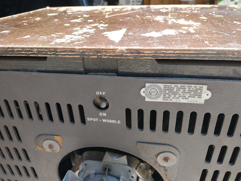 A little research revealed the the Mazda CRM171 picture tube is pretty much the same as a common US 17", 70 degree, 12 pin base CRT. Aluminized with an external ion trap magnet. 12.6 volt, 300 mA filament. I'm thinking I can make something like a 17BP4 or 17HP4 work by using a 6.3 VAC filament transformer. I'd need to modify the HV connector, but otherwise the dimensions look very similar. Even the base connector and pinout are the same  It is a hot chassis, series strung design using 300mA tubes. 200-250 volts AC/DC. There is a plug matrix and big, tapped power resistor to select the operating voltage.  It's actually fairly clean and looks to be complete inside.  

|
|
#2
08-09-2022, 01:18 AM
|
||||
|
||||
|
All the Ekco sets from this period are good sets and restore well. The plastic LOPT (flyback) housing looks in good condition which is very rare. They usually disintegrate. A strange plastic, clear thermosetting.
Although it looks rough, it's quite likely to work after replacing all the wax capacitors. There's one hidden in the tuner that's a bit tricky to access. Assuming you can find a CRT, the hardest part to replace will be the broken/missing knob. Not readily found even back in the UK. I wonder how a set like this found its way across the Atlantic. Service data is on Trader Sheet 1278/T115 which is common to to a number of Ekco sets from this era. The 267/1 was released in September 1956, the month of my birth. If you can't easily find a copy of the Trader Sheet please mesage me. Last edited by ppppenguin; 08-09-2022 at 01:23 AM.
|
|
#3
08-10-2022, 12:52 PM
|
||||
|
||||
|
Thanks for the offer. I was able to get very high quality, inexpensive scans of both the manufacturers service info and the Trader Sheet here: https://www.service-data.com/
I have a much better understanding of what I'm looking at now  The CRT base is compatible with US CRTs so I should be able to use an 8XP4 on the workbench. 
|
|
#4
08-11-2022, 12:29 AM
|
||||
|
||||
|
This indeed looks like an interesting project. I wonder how a 405 line television ending up on this side of the Atlantic? I suspect the unwitting owner when emigrating to the US years ago did not know about TV standards.
It will be fun building a modulator as it is positive rather than negative modulation with AM sound. And with the converters made with FPGAs, I wonder if anyone had ever considered or produced a convertor for 525 59.94 to 405 50Hz ? As for the CRT, it looks like the 17BP4 can be made to fit. I also noticed it has a spot wobble switch on the back! Never knew that spot wobble was ever applied to consumer receivers. Last edited by Penthode; 08-11-2022 at 12:39 AM.
|
|
#5
08-11-2022, 01:16 AM
|
||||
|
||||
|
Spot wobble was used in a few UK sets. With larger screens the 405 line structure was very visible. Still not common.
The Aurora WC-01, of which only a few were made, will convert NTSC to 405/50. The modulator output is correct too. You would be very lucky to find one. The field timebase will lock to 60Hz if necessary. There are various published designs of System A modulators. From simple designs using crystals and 1496 balanced modulator chips to the universal modulator chips used in the Auroras. It's more or less essential to use a separate sound modulator, whichever approach you use. I wrote this article in 1989: https://www.borinsky.co.uk/simple_channel.html David Looser's design is similar but earlier: https://www.thevalvepage.com/project...at/modulat.htm Several people in the UK and Europe have generated 405 (and other standards) by using a VGA output from a graphics card and setting the modeline. I have never tried this. I think there is some writing about this on my friend Peter Scott's site: http://www.nostalgiatech.co.uk/
|
| Audiokarma |
|
#6
08-11-2022, 08:42 AM
|
||||
|
||||
|
Bob, you might want to contact the folks at the ETF museum. Pretty sure they have some 405 line sets they run.
BTW folks, I've never heard of a wobble switch. What is the deal?
|
|
#7
08-11-2022, 09:32 AM
|
||||
|
||||
|
Hi to all,
Hi Bandersen, I replied to your enquiry about your Ekco TV on the ARF forum, but maybe you haven't had time to read the thread since you posted : https://antiqueradios.com/forums/vie...p?f=3&t=416233 The Aurora SCRF "economical" series of standards converters do not change the frame rate between 25 FPS and 30FPS (or vice-versa), in your case, the British model converts 625/25 to 405/25. There is no model aside from the World Converter which will accept 525/30 and convert to 405/25. In my opinion, you could use the UK model (with built-in RF System A modulator) feeding it from a cheap Euro DVD player with 625/25 baseband output & a Zone 2 (Europe) DVD disk. There are also relatively cheap true PAL/SECAM/NTSC Standards Converters (consumer grade) which really change lineage and frame rate. See brands such as Atlona on E-Bay in video accessories section. I've run a bunch of them in my personal systems and they do an astonishing job vs what used to be 50K-100K$ +Broadcast converters. or Attempt to run the Ekco with 405/30, just with a slight adjustment to the V-Hold frequency. However, i do not know if the UK SCRF model will sync with a 30 Hz frame rate. Maybe Darryl H. (Aurora designer) will read this thread... Best Regards jhalphen Paris/France Last edited by jhalphen; 08-11-2022 at 09:40 AM.
|
|
#8
08-11-2022, 09:56 AM
|
||||
|
||||
|
Thank you for all the advice. I have also been looking around on eBay UK for a vintage 405 line test pattern generator without any luck.
I find that surprising given how common they are in the US. What did servicemen in the UK use back in the day for test patterns?
|
|
#9
08-11-2022, 03:25 PM
|
||||
|
||||
|
Hi to all,
Hi Bandersen, Your best chance to find a 405 line test generator would be to place a request on the UK Vintage (UKVRR) "Wanted" section. https://www.vintage-radio.net/forum/...splay.php?f=28 Tube-type generators were in full swing from the 50s/60s, OK, 405 started in 1936. 625 (BBC2) started in 1964 so 405 started waning. First generation color sets (1967-1970) were dual standard but complicated and not very reliable. When BBC1 & ITV were duplicated on 625/color/UHF, TVs became single standard and only shops who had been in TV repair for 20/30 years still had 405 test gear. 405 was finally switched off in 1983. With a bit of luck, an old 405 generator might have an external video input to use it as a System A Modulator. An interesting thread on another UK TV forum about a 405 video generator using a PIC microchip. 7 pages, last post 2016 : https://www.radios-tv.co.uk/communit...ern-generator/ Best Regards jhalphen Paris/France Last edited by jhalphen; 08-11-2022 at 03:38 PM.
|
|
#10
08-11-2022, 05:48 PM
|
||||
|
||||
|
Quote:
Sounds like it basically blurs the lines in a vertical direction to remove the slight gap between lines.
|
| Audiokarma |
|
#11
08-11-2022, 07:03 PM
|
||||
|
||||
|
This website has a good article on the "spot wobble" circuit.
It is a stand-alone oscillator that drives a pair of coils positioned around the CRT neck so as to add a little vertical deflection to the electron beam. A frequency of around 12.5 MHz is used to avoid interference with reception and IF circuits. http://www.thevalvepage.com/teletech/wobble/wobble.htm
|
|
#12
08-11-2022, 11:19 PM
|
||||
|
||||
|
Quote:
__________________
Tom C. Zenith: The quality stays in EVEN after the name falls off! What I want. --> http://www.videokarma.org/showpost.p...62&postcount=4
|
|
#13
08-12-2022, 01:14 AM
|
||||
|
||||
|
Quote:
If you go to the World radio history site, find Practical Television magazine(later just Television) a very widely read magazine in the TV repair community. Search "pattern generator" in the 50's and 60's issues, lots of designs and circuits were around. https://worldradiohistory.com/Practi...n_Magazine.htm
|
|
#14
08-12-2022, 01:33 AM
|
||||
|
||||
|
Quote:
generator. If you also search his videos he gets various 405 sets working. https://youtu.be/hf8c2mDopTI The Sony TV in the video is very useful for testing 405 circuits, the non monitor version is the TV 990UB but is fairly easily converted to video input. The previous model TV 9-306UB from 1966 is not as reliable as the 990,its on the cover of the Beatles Sgt Pepper album, bottom right behind a plant!
|
|
#15
08-12-2022, 04:01 AM
|
||||
|
||||
|
Bob, that is an impressive rectifier you have there.
|
| Audiokarma |
 |
|
|


 Linear Mode

