
 |
|
#46
|
||||
|
||||
|
Quote:
I'm going to tug the chassis out tomorrow and add in the two needed wires and the cap so I can check the current. I want to make sure it's below 220 so I can baby this fly. I ran the set again for a few minutes, and it's stable and very bright. I'm gonna get together with Electronic M soon hopefully, and I think we can hammer out the last of the sets issues and make it work fully again. |
|
#47
|
||||
|
||||
|
That is not far off from how it should be running.
One thing that may be worth wile when doing the current check is to add a 1/4 amp fuse to the cathode....It will lend some protection and if you (or I) mount the fuse holder above chassis it will facilitate future current checks and adjustment (just pull the fuse and connect the meter).
__________________
Tom C. Zenith: The quality stays in EVEN after the name falls off! What I want. --> http://www.videokarma.org/showpost.p...62&postcount=4 |
|
#48
|
||||
|
||||
|
Quote:
|
|
#49
|
|||
|
|||
|
Teamwork. I like that!
Only 2-1/2 weeks to the next WARCI swap. See you guys then. . |
|
#50
|
||||
|
||||
|
It may have been suffering low HV before, but no longer. The new focus rectifier, and the shuffling of tubes... And I also cleaned up some dust build up inside the HV cup on top of the flyback box since there was some arcing in there, and I also changed out the anode lead to the CRT with a 50kV rated wire from an old computer monitor, which took care of all the arcing, and makes a nice connection to the CRT, as well.
(and a minor adjustment to my meter so the needle would stop sticking) 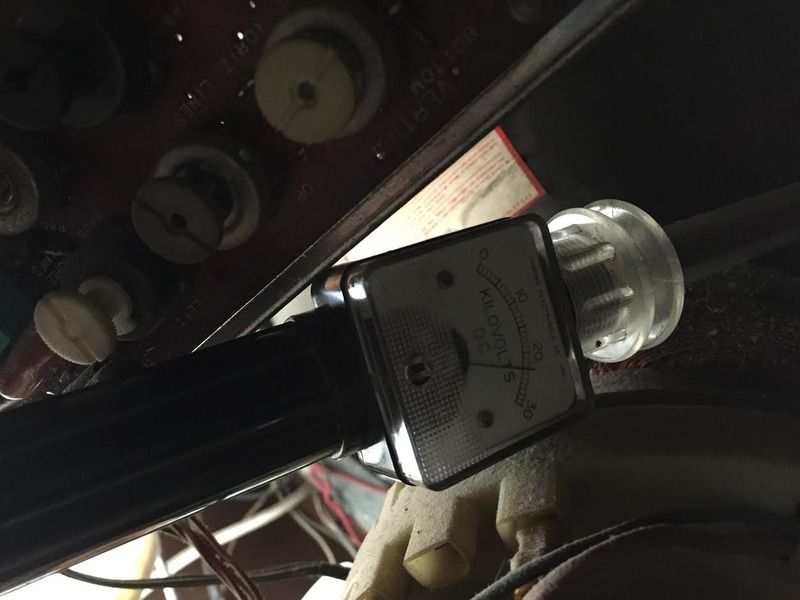 25kV! Now, the Hi-Volt adjust is cranked open all the way, so that could be something else, time will tell once it gets more issues, and caps changed. Now for everything else. One step at a time. This was a big step for me, very excited to see color, 25kV on the meter, and a bright stable image. This will be a nice set again soon! Last edited by Arcanine; 10-22-2015 at 03:14 AM. |
| Audiokarma |
|
#51
|
||||
|
||||
|
Could be the 1.5 meg resistors around the hv pot, may have drifted.
|
|
#52
|
||||
|
||||
|
Quote:
__________________
Brian USN RET (Avionics / Cal) CET- Consumer Repair and Avionics ('88) "Capacitor Cosmetologist since '79" When fuses go to work, they quit! |
|
#53
|
||||
|
||||
|
I'm overhauling it for Arcanine. So rather than fill my PM box and keep it hidden, here is a public status update.
I started work on it today. As gotten screen shots: 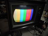 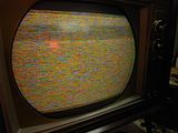 As can be seen the grayscale was very yellow. I also had to tweak the chroma osc. to get the color bars shot. I could not get setup lines with the service switch and had to resort to playing with the brightness and CRT bias switch to get them.....The blue was still VERY weak with it's control maxed (had to douse the lights to balance the lines with the G2 knobs)....I'm probably going to test the gun biases later to see if something is messing with the blue. That got me here:  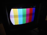 I decided to verify HV level on my probe. With the set running on 117VAC it's producing 23.5KV, which is within the 22-24KV listed in the sam's. I removed the chassis and decided to look at the ruined power switch. The shaft of the vol pot/power switch on the donor CTC-20 chassis was 1/2" too short, and the switch was different so that was eliminated as an option. Opening the original switch revealed that a piece of black phenolic (SP?) that connects the switch contacts to the shaft broke. Attempt to duplicate it failed due to limited tools and lack of knowledge of the shape of the damaged part. I then remembered I had some spare pots with similar switch shells. None of my spare pots had the right shaft length so I tried to transplant the switch section alone. One had different guts that I ruined trying to adapt to the original. The second was identical to the original switch section and I was able to mount it successfully. It works well, and no one would ever think it was a replacement. The white piece on the original shaft in the picture is what the broken black piece in the original switch should have looked like. 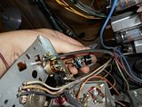 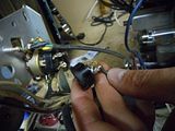 Now that the grayscale is right and the power switch works again, it is on to other work.....Like changing original caps of types I do not trust, going over the vertical circuit, and some adjustments, etc.
__________________
Tom C. Zenith: The quality stays in EVEN after the name falls off! What I want. --> http://www.videokarma.org/showpost.p...62&postcount=4 |
|
#54
|
||||
|
||||
|
Looking good! What's the HOT cathode current running?
Always replace the cap attached to the cathode of the 'GF7 - that cap, more than any will cause problems with the vertical. Also go over the ground eyelets on the boards. Vertical / horizontal sync problems are generally caused by resistors way out of tolerance. I've restored three CTC16 sets, and outside of electros, the cathode cap, the sync resistors, and a thermistor or two, I've never replaced a single film cap. Also clean the pins on the IF tubes - video will suffer If problems there. Like I said, looking real good!!
__________________
Brian USN RET (Avionics / Cal) CET- Consumer Repair and Avionics ('88) "Capacitor Cosmetologist since '79" When fuses go to work, they quit! |
|
#55
|
||||
|
||||
|
Oh wow. Those colors are really good. You really managed to get rid of that yellow it was suffering.
Excited to see the progress. This was just one of those things, I was so let down when I got it home and it almost was completely dead, I was so disappointed I didn't find my self wanting to work on it. I got it as far as proper HV, and color on the screen then passed it on to you. When we tested my CRT, didn't it show all the guns were pretty good? Seems strange blue doesn't want to play nice. Last edited by Arcanine; 10-28-2015 at 11:45 PM. |
| Audiokarma |
|
#56
|
||||
|
||||
|
Quote:
__________________
Tom C. Zenith: The quality stays in EVEN after the name falls off! What I want. --> http://www.videokarma.org/showpost.p...62&postcount=4 |
|
#57
|
||||
|
||||
|
It may wake up. I have no idea how many years that TV was sleeping and how long that CRT went unused. It seems like it has a hell of a picture.
|
|
#58
|
||||
|
||||
|
Red eye status update.
I've found why the screens were funky. The 1020V boost was 200-300V low. The 100K resistor between the rectifier and it's loads was 2.5X rated value. Replacing it got it half way back to spec. Replacing the boost diode with 2 1.5KV PIV rated silicon ones (1 probably would have been enough, but there is no kill like overkill  ) in series brought it within 35V of spec.....I'll call that close enough of a tolerance for my taste. Now I can back the CRT bias switch off a click and still get a bright blue set up line. ) in series brought it within 35V of spec.....I'll call that close enough of a tolerance for my taste. Now I can back the CRT bias switch off a click and still get a bright blue set up line.  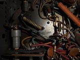  I replaced the three tubular ceramic Elmenco caps with modern parts (I've seen enough bad not to trust them). The .01 400 red tubular plastic H osc. cap next to the coil also has been replaced as a precaution. 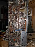 The grounds on the video and sweep boards got a 150W iron touch up, and I also reflowed the some of chroma osc. traces (she has not lost color synch since last time). I added the HOT cathode fuse holder, but I don't have any fuses down near the 1/4A range so it is a place holder until you pop one in. Cathode current dipped at about 200-205mA which seems decent. 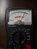 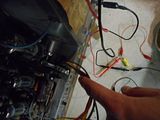 I checked every resistor in the vertical section under the 2Meg max of my DMM and all were within rated tolerance. The V Out cathode cap was re-replaced with a new 47uF 160V replacement that is closer to the original 50u 150V cap that Arcanine replaced with a 100u 400V. The 80uF 450V off the vertical output Xfmr tested fine and B+ to it looks good. Hoping the Boost fix would bring it back I powered it up with no change in vert. Some tube rolling got me this: 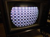 I think my plan of attack is going to be lift one leg of the high resistors in the vertical so my chinese component tester (which has a higher resistance range, but is more interested in the caps in the circuit) can focus on the resistors and if that fails to find fault start testing/changing the vertical stage drop caps. Unfortunately while going thru the spare tubes (to find another vertical tube) one of the H outs Arcanine left with me managed to roll off the table and bust it's self on the floor.  I'm sorry dude, I should have been more careful. I'm sorry dude, I should have been more careful.
__________________
Tom C. Zenith: The quality stays in EVEN after the name falls off! What I want. --> http://www.videokarma.org/showpost.p...62&postcount=4 |
|
#59
|
|||
|
|||
|
Quote:
As for the tube rolling off of the counter, well, I have been not only in that church but also in the same pew as well. Usually with something like a sweep tube, audio output tube (not 50C5, think ... 7027A etc.) or Telefunken 12AX7/ECC83. Yes, very frustrating and especially when we try so hard to not have it happen! Again, looking great! |
|
#60
|
||||
|
||||
|
Quote:
And which tube was it? Was it the tall RCA 6JE6? Or was it a Sylvania 6LQ6? If it was the Sylvania don't lose any sleep over it. If it was the RCA, well, better start sweating! Haha nah don't worry I'm kidding, accidents happen. I have a couple more of those here. |
| Audiokarma |
 |
| Thread Tools | |
| Display Modes | |
|
|