Videokarma.org

Go Back   Videokarma.org TV - Video - Vintage Television & Radio Forums > Early Color Television

We appreciate your help

in keeping this site going.
Reply
 
Thread Tools Display Modes
  #61  
Old 12-28-2023, 11:17 PM
old_tv_nut's Avatar
old_tv_nut old_tv_nut is offline
See yourself on Color TV!
 
Join Date: Jul 2004
Location: Rancho Sahuarita
Posts: 7,207
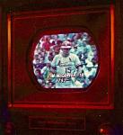
"Out of curiosity I adjusted L1 (41.25mc trap) and L3 (39.75 trap) to their max and I was able to get the below curve, all other coils and transformers I left as-is. It seems like if I had a bit more adjustment in the coils I could get the response curve to dip between the 39.75mc and 41.25mc markers."

When you say dip do you mean lower on the scope screen (actually an increase in signal)? Matching that blip is not important. What is important is that the response at
42.75 and 45.0 are equal, 45.75 is at 50%, 39.75 is practically zero (high on the scope trace) and 41.24 is high on the trace, at -24 dB or greater, which means less than 6% of the peak response.
__________________
www.bretl.com
Old TV literature, New York World's Fair, and other miscellany
Reply With Quote
  #62  
Old 12-28-2023, 11:21 PM
old_tv_nut's Avatar
old_tv_nut old_tv_nut is offline
See yourself on Color TV!
 
Join Date: Jul 2004
Location: Rancho Sahuarita
Posts: 7,207
Also, 45.75 should be at 25 or 30% per the drawing, not 15% as in your last trace.

Correction: I meant 41.75, whihc I was reminded by later post is actually 41.67 in the B&K.
__________________
www.bretl.com
Old TV literature, New York World's Fair, and other miscellany

Last edited by old_tv_nut; 12-29-2023 at 11:00 AM.
Reply With Quote
  #63  
Old 12-29-2023, 09:41 AM
bhegges bhegges is offline
VideoKarma Member
 
Join Date: Oct 2008
Location: Sioux Falls, SD
Posts: 135
I think I got it. Note the B&K 415 outputs a 41.67mc vs 41.75mc marker. I maybe could try to reduce the 47.25mc marker as it is not quite at zero. The peak to peak signals at each test point is still an interesting element as changing the amount of signal from the B&k 415 going into the tuner does change the response curves. I might try to measure the tv when it is normally running to see what I get.

C1


C2
Reply With Quote
  #64  
Old 12-29-2023, 11:00 AM
old_tv_nut's Avatar
old_tv_nut old_tv_nut is offline
See yourself on Color TV!
 
Join Date: Jul 2004
Location: Rancho Sahuarita
Posts: 7,207
I think this looks excellent.
__________________
www.bretl.com
Old TV literature, New York World's Fair, and other miscellany
Reply With Quote
  #65  
Old 12-29-2023, 04:20 PM
bhegges bhegges is offline
VideoKarma Member
 
Join Date: Oct 2008
Location: Sioux Falls, SD
Posts: 135
Next up: Sound and 4.5mc trap, these went well. See below for directions:

Sound
  1. Tune in a station, note I used a DVD player that I could pause and then turn up the volume to hear the noise
  2. Added an attenuator in-line with the converter box and tuner, set to 20db attenuation
  3. Adjust the quadrature coil, intercarrier coil, sound take off coil and buzz potentiometer to minimize hum/buzz/hiss

4.5 Trap
  1. Tune in a station
  2. Color switch on
  3. Ground test point K
  4. Connect the standard oscilloscope probe to test point K
  5. De-tune slightly with the fine tuning, when doing this I could see the below line on the scope fatten
  6. Adjust L7 to minimize the 920kc beat

Chassis test point and component locations:


Reply With Quote
Audiokarma
  #66  
Old 12-29-2023, 05:49 PM
bhegges bhegges is offline
VideoKarma Member
 
Join Date: Oct 2008
Location: Sioux Falls, SD
Posts: 135
Moving right along to the Color Amplifier alignment, below are the steps I took. Also posted are the Zenith Service manual and SAMS directions.
  • Disconnect the tuner antenna input and set tuner in between channels
  • Color switch on, color level set to the halfway point
  • SAMS directions say to set the hue to the halfway point so I did this too
  • Ground test point K
  • Connect -6 volt bias to test point Q
  • Connect the oscilloscope to the B&K 415 via the Horz and Vert inputs
  • Connect demodulator probe (PR-151) from the B&K 425 Demod connector to test point U which is the cathode of the R-Y demodulator tube
  • B&K 415 output set to Chroma, function set to Video
  • Connect the B&K 415 signal to test point C1, I used the supplied RF Cable probe (TP-41) set to 75 ohms
  • Set the sweep center frequency to 3.6mc, I kept the sweep width at max
  • Note the B&K 415 does not have a 3.63mc marker

Here is my starting point, mostly a mess. The 3.0mc marker needs a lot of gain, and the either the 3.58mc has too much gain or the 4.1mc needs more gain.


Zenith Service Manual CM-105 (25MC33 Chassis)


SAMS directions (Folder 757, Set 4)

Last edited by bhegges; 12-29-2023 at 08:42 PM.
Reply With Quote
  #67  
Old 12-29-2023, 08:52 PM
bhegges bhegges is offline
VideoKarma Member
 
Join Date: Oct 2008
Location: Sioux Falls, SD
Posts: 135
For now I skipped the Zenith direction around replacing the 8.2k damping resistors and simply followed SAMS, unfortunately I could not get the proper response curve by adjusting L17 and L19. first up I will try some different 6KT8 tubes before pulling the chassis out to further investigate.

See the following post for the color circuit schematic from the Zenith Service manual. I have marked in red the relevant Zenith and SAMS coils and test points. Highlighted in green are out of spec parts I earlier replaced, note A3 is an integrator (Zenith part number 87-9), I edited the schematic to show the parts used to replace.

Last edited by bhegges; 12-29-2023 at 09:13 PM.
Reply With Quote
  #68  
Old 12-29-2023, 08:53 PM
bhegges bhegges is offline
VideoKarma Member
 
Join Date: Oct 2008
Location: Sioux Falls, SD
Posts: 135
Reply With Quote
  #69  
Old 12-29-2023, 09:36 PM
bhegges bhegges is offline
VideoKarma Member
 
Join Date: Oct 2008
Location: Sioux Falls, SD
Posts: 135
I tried swapping out the two 6KT8 color amp tubes and seen some improvement from changing the first color amp tube (V6) but still not getting enough response at the 3.0 marker.

Reply With Quote
  #70  
Old 12-30-2023, 02:07 PM
jr_tech's Avatar
jr_tech jr_tech is offline
VideoKarma Member
 
Join Date: Sep 2009
Posts: 4,515
I’m confused... since the scope photo is posted upside down, what is the marker directly above the Tektronix “x”?

jr
Reply With Quote
Audiokarma
  #71  
Old 12-30-2023, 02:26 PM
bhegges bhegges is offline
VideoKarma Member
 
Join Date: Oct 2008
Location: Sioux Falls, SD
Posts: 135
The lower right marker is the 4.5mc marker. I flipped the scope picture so to match the Zenith Service manual figure 14 reference. See my above post for the picture.
Reply With Quote
  #72  
Old 12-30-2023, 03:12 PM
old_tv_nut's Avatar
old_tv_nut old_tv_nut is offline
See yourself on Color TV!
 
Join Date: Jul 2004
Location: Rancho Sahuarita
Posts: 7,207
How much does the 3.08 MHz marker move when you adjust L17/A26?
__________________
www.bretl.com
Old TV literature, New York World's Fair, and other miscellany
Reply With Quote
  #73  
Old 12-31-2023, 11:21 AM
bhegges bhegges is offline
VideoKarma Member
 
Join Date: Oct 2008
Location: Sioux Falls, SD
Posts: 135
Here are the curves when adjusting L17 (1st Color Amp Plate Coil) for min and max 3.08mc response:


Also for reference below are the responses when adjusting L19 (2nd Color Amp Plate Coil) which is used to minimize the 3.58,mc response, pics showing min, middle, and max adjustments:


In looking over the full color alignment directions the Zenith manual notes to perform the color amplifier alignment first via adjusting L17 and L19 as the color sync alignment will be affected. Also interesting that SAMS alignment directions are the opposite and have you do the color amplifier alignment last.

Question how much affect will the remaining alignment affect the color amplifier response? I am curious if there is an issue with the color amplifier circuit or if the issue is further misalignment. I might pull the chassis and double check to ensure I didn't make any repair mistakes. The earlier posted schematics highlights replaced parts, mostly way out of spec resistors and then film capacitors.

Note there are a couple of suspect ceramic capacitors that in-circuit measure over the 10% spec:
  • C54 - .0047uf 10% 500v measures .003739uf 20% low, maybe an issue?
  • C55 - 47pf 10% N75 500v temp measures 54pf 16% high probably good if I pull a lead to measures
  • C59- .001uf 10% 1kv measures 840pf 16% low, also maybe a problem?
  • C61- .001uf 10% 1kv measures way high probably getting in parallel capacitance somewhere

Last edited by bhegges; 12-31-2023 at 11:33 AM.
Reply With Quote
  #74  
Old 12-31-2023, 12:37 PM
old_tv_nut's Avatar
old_tv_nut old_tv_nut is offline
See yourself on Color TV!
 
Join Date: Jul 2004
Location: Rancho Sahuarita
Posts: 7,207
C54, C59, c61 are bypass caps not likely to be a problem unless far too small.
C55 looks like it could load T9, maybe check it and the resistors on the other end of it in the burst amp circuit?

I forgot - did you check the 8200 ohm damping resistor connected to T19? How about C58?
__________________
www.bretl.com
Old TV literature, New York World's Fair, and other miscellany
Reply With Quote
  #75  
Old 12-31-2023, 12:47 PM
old_tv_nut's Avatar
old_tv_nut old_tv_nut is offline
See yourself on Color TV!
 
Join Date: Jul 2004
Location: Rancho Sahuarita
Posts: 7,207
Have you also checked all T19 windings to make sure nothing is open?
__________________
www.bretl.com
Old TV literature, New York World's Fair, and other miscellany
Reply With Quote
Audiokarma
Reply


Posting Rules
You may not post new threads
You may not post replies
You may not post attachments
You may not edit your posts

BB code is On
Smilies are On
[IMG] code is On
HTML code is Off

Forum Jump


All times are GMT -5. The time now is 01:41 PM.


Powered by vBulletin® Version 3.8.4
Copyright ©2000 - 2024, Jelsoft Enterprises Ltd.
©Copyright 2012 VideoKarma.org, All rights reserved.