
|
|
|
#46
 06-07-2016, 08:29 PM
|
||||
|
||||
|
I was wondering about the "most complicated kit" title. This is certainly the most complicated Heathkit I have had the fun of putting together, with the second being a "Hero Jr." robot.. I think the later GR-2000 and GR-2001 sets with the on screen display beat this one by a bit, with the addition of several digital boards for the advanced features.
The other contenders for the complexity prize would possibly be the Heath/Thomas electronic organs, or possibly the H1 Analog Computer: http://www.technikum29.de/en/computer/analog 
|
|
#47
06-08-2016, 08:46 PM
|
||||
|
||||
|
The chassis assembly is completed with a handful of electrical connections on the top side of the chassis, to the IF module and power supply filter choke.
The 9 previously completed PCB modules are then installed into their proper locations, and the chassis set aside for final assembly with the rest of the set. These pics are of the top side of the completed chassis, with all modules installed. Up next, assembling the VHF/UHF tuner cluster and control panel...
|
|
#48
06-08-2016, 10:52 PM
|
||||
|
||||
 Wow! Wow!
__________________
My TV page and YouTube channel Kyocera R-661, Yamaha RX-V2200 National Panasonic SA-5800 Sansui 1000a, 1000, SAX-200, 5050, 9090DB, 881, SR-636, SC-3000, AT-20 Pioneer SX-939, ER-420, SM-B201 Motorola SK77W-2Z tube console McIntosh MC2205, C26 
|
|
#49
06-09-2016, 06:12 PM
|
||||
|
||||
|
Interesting that it uses a HV rect tube.
__________________
Tom C. Zenith: The quality stays in EVEN after the name falls off! What I want. --> http://www.videokarma.org/showpost.p...62&postcount=4
|
|
#50
06-09-2016, 06:29 PM
|
||||
|
||||
|
Probably has to do with the year it was first available-1969. I don't think there was a reliable solid-state substitute yet.
In 1974 I went to work for Varo Inc. and among the things they manufactured were solid-state high voltage rectifiers and triplers for TVs. By then they were reliable and common.
|
| Audiokarma |
|
#51
06-09-2016, 07:21 PM
|
||||
|
||||
|
Varo pretty much owned the market on those things, didn't they? I think they were the first to produce them. I agree the 1969 introduction of this model would have been just a bit early for SS. I assume the GR2000 series sets used a solid state HV rect or tripler?
I have an ECG solid state replacement here which I think would work in this set should the 3CU3 ever give problems.
|
|
#52
06-12-2016, 10:28 PM
|
||||
|
||||
|
Onto the next assembly manual, covering the assembly of the Tuner cluster/Control panel. The manual is divided into 2 sections, and the builder follows the half with or without the remote control option as applicable.
Work starts out as more mechanical assembly. The VHF and UHF tuners come preassembled, and are mounted into a metal subchassis. The tuner drive motor and gearbox get attached, along with numerous terminal strips and a large oil filled capacitor (4 uF, 370V) used for reversing the tuner drive motor. The supplied capacitor was a Sprague "Chlorinol" capacitor, which was a trademark for polychlorinated biphenyl, or PCB. All the pots get attached to a bracket, which is then mated to the front subpanel and the tuner chassis, completing the mechanical assembly. Because I am installing the remote option, drive motors get installed onto the back side of the color and tint pots to allow remote operation. The UHF and VHF channel indicator dials are backlighted by incandescent lamps, and driven via a small timing belt drive. The VHF fine tuning is driven with a ballchain drive system. 4 pushbutton switches are installed for power, channel up/down, and UHF/VHF select. The wiring is almost completely prefabricated harnesses, which are quite long and make for a real pain on the bench. The unit ends up with quite a wad of wiring attached. The final part of the assembly is the stuffing of a small PC board which they call the "UHF" board, but what it really handles is the switching between UHF and VHF tuners, and driving the appropriate dial backlight for the selected band. The board is connected to the chassis via a 15 pin Molex connector which supports the entire board. While Heath sent a 15 pin Molex connector which I dutifully installed, It wasn't until trying to plug the board in that I discovered that the WRONG GENDER of connector shell was supplied! Luckily, I had a proper connector shell, as well as the pin extraction tool to remove the contacts from the supplied shell, and reinsert them into the proper one. The board survived the desoldering and resoldering just fine, and the tuner cluster was completed in 3 bench sessions totaling around 5 hours.
|
|
#54
06-13-2016, 07:36 PM
|
||||
|
||||
|
Onto book #4, covering assembly of the CRT, mask, and chassis frame.
I began the process by building a temporary "T" extension (3/4" plywood and 2x4 legs) onto my workbench to provide enough room to work on the assembled set. Most of the projects I tackle in my shop are a good bit smaller than this beast!  First up, I decided to actually test the CRT to make sure it was still electrically good. The CRT carton was pretty well destroyed by moisture, and the tube itself has a nasty cataract extending 3-4 inches in toward the center in a few spots. Assuming the set makes a good picture, a cataract removal or (preferably) a CRT replacement can be pursued later. The supplied tube is an RCA 25VABP22, but the manual refers to a 25VADP22. Comparing datasheets shows the tubes are pretty much identical, with the later VADP having a "Temperature Compensated" (Invar?) shadow mask for improved purity. I seem to remember that most of the 25V-series tubes were fairly interchangeable, with minor differences like black matrix, rare earth, mounting ears, etc. Firing up the tester, the tube was a bit slow to warm up after sleeping all these years, but after a few minutes warmup the guns balanced perfectly, with emission and life test readings consistent with a NOS tube.  Assembly begins by placing the plastic CRT mask face down on supports (4 blocks of 2x4), and lining the inside of the mask surface (where the edges of the CRT faceplate rest) with aluminum foil tape as an electrostatic drain. The provided roll of 3M foil tape was still perfectly usable after 4 decades in storage. The foil is carefully overlapped in the corners, and folded over to make contact with the CRT mounting hardware. The CRT is then placed into the mask opening, making sure that the anode contact faces the top edge of the mask. The CRT clamps and straps are prepared by adding adhesive felt pads (also amazingly viable despite age) and rubber cushions at the points where the clamps bear against the glass. the clamps are carefully drawn down tight in several stages until they bottom against the mask, then the strap screws are tightened to clamp the tube into place. A long length of bare solid wire and a coil spring are installed as a grounding contact for the outside dag coating, and the degaussing coil is wrapped around the tube in a very carefully specified pattern (to assure even magnetic field over the mask area), and anchored in place with cable ties. Next up--final chassis assembly and moving toward "First Light".... Last edited by N2IXK; 06-13-2016 at 07:41 PM.
|
|
#55
06-13-2016, 08:09 PM
|
||||
|
||||
|
I can't wait to see this up and running! Great job!
__________________
My TV page and YouTube channel Kyocera R-661, Yamaha RX-V2200 National Panasonic SA-5800 Sansui 1000a, 1000, SAX-200, 5050, 9090DB, 881, SR-636, SC-3000, AT-20 Pioneer SX-939, ER-420, SM-B201 Motorola SK77W-2Z tube console McIntosh MC2205, C26
|
| Audiokarma |
|
#57
06-14-2016, 01:53 PM
|
||||
|
||||
|
Great work no question. It's always a pleasure to build a device with your own hands. I built a few custom devices at work and know how much time it takes because I had to drill every hole and crimp every connector by hand. Did you clean the pcbs with spiritus after soldering and count the hour´s it takes? Greetings and good luck!
|
|
#58
06-14-2016, 09:43 PM
|
||||
|
||||
|
Yes, the remote is pretty fugly. The "thousand island dressing" color scheme doesn't help...
 I did clean the modules with flux remover after soldering. I haven't been keeping all that close a count of hours, but 40-45 hours to this point is my best guesstimate, not including the time inventorying the parts, ordering replacements, and related activities. After installing the CRT into the mask, the 4 sides of the chassis frame/magnetic shield are attached to the mask and bolted together forming a rigid box structure. The dag ground from the CRT assembly is grounded to this frame. The deflection yoke is installed into the "flowerpot" style holder, and installed onto the CRT neck. The completed chassis is hung on its hinges, and the degaussing leads and CRT anode wire are connected, before closing the chassis. I elected to replace the somewhat stiff and degraded anode cap with a nice silicone rubber one salvaged from a discarded BPC set. After the chassis is installed, the entire framework and tube was thoroughly degaussed (using a real coil, not the dinky external one provided with the kit), and the convergence magnets/coils and blue lateral/purity magnets were installed, along with the CRT socket. The convergence board, tuner cluster, and "Troubleshooter" meter are hung on screws in the framework for the initial test/adjustment procedures, and all the interconnecting cables plugged in. This completes the assembly of the set! Up next, using the "Troubleshooter" to check for problems, and power gets applied for the first time....
|
|
#59
06-15-2016, 12:05 AM
|
||||
|
||||
|
Light that sukka!!!
 SR
|
|
#60
06-16-2016, 08:05 PM
|
||||
|
||||
|
Testing begins with a series of testing flowcharts, where the builder uses the provided VOM to make a series of resistance tests to verify that no major shorts or miswiring exists. Tests were made using both the "Troubleshooter" VOM and a DMM (Fluke 87). As Heath gave no specific resistance values, just which area (A-E) the troubleshooter needle should indicate for each test, I noted the actual resistance reading taken with the DMM in my build notes.
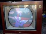
You test the AC line circuitry first, checking for continuity and shorts to chassis ground. Then the various main power supply rails are checked for resistance to ground, to rule out shorts or reversed polarity components that might cause damage at powerup. About a dozen tests all together, and all passed with flying colors.  At this point, you preset the brightness, brightness limiter, drive, screen and kine bias controls as specified, and unplug the CRT socket. The set gets connected to 120 vac, and the switch is thrown..... No bang....  The gentle crackling sound of HV supply coming alive!  No smoke or bad smells... Back to the testing charts, where measurements are made of cathode, G1 and G2 voltages, and a couple power supply rails. All well within the specs... An occasional snap/crackle was noted from inside the HV cage and traced to a bit of cardboard packing material that was trapped under the edge of the HV rectifier tube socket.  The set is then powered down, and the CRT socket connected. Ready for "first light" tomorrow night, when my chroma board helper and her mom are dropping by for dinner and to watch this thing come to life. The suspense is killing me...  Not much in the way of pics for this post. I hope some screen shots will be taken tomorrow night....
Last edited by N2IXK; 06-16-2016 at 08:09 PM.
|
| Audiokarma |
 |
| Thread Tools | |
| Display Modes | |
|
|


 Linear Mode

