
|
|
|
#77
 04-08-2011, 12:46 AM
|
||||
|
||||
|
Quote:

|
|
#78
04-11-2011, 09:45 PM
|
||||
|
||||
|
Good news! A fellow restorer just emailed me that he's found a Philco 3/4 inch voice coil with original spider with wires attached! He's also offered to recone my speaker

Last edited by bandersen; 04-14-2011 at 02:45 PM.
|
|
#79
04-14-2011, 08:43 AM
|
||||
|
||||
|
Wow, Bob, You's a lucky ol' dog!
Parts plus a re-cone. I wonder how they make those cones? Some kind of form and press? Buzz 
__________________
______________________ Buzzsaaw Sunlitedreams.com
|
|
#80
04-21-2011, 01:04 AM
|
||||
|
||||
|
Quote:
I cleaned off all the old cone remains and lots of dust & dirt. Also used some naval jelly to remove rust and shipped it off for reconing. 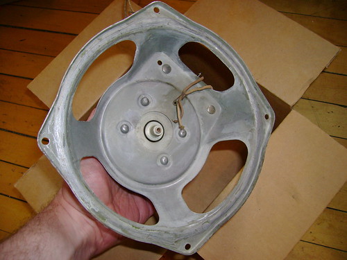
|
| Audiokarma |
|
#81
04-21-2011, 06:23 PM
|
||||
|
||||
|
That looks great! and should make it easier for them to re-cone.
Glass of glue anyone?  It would be fun to visit one of those re-coning shops. Buzz
__________________
______________________ Buzzsaaw Sunlitedreams.com
|
|
#82
04-25-2011, 10:07 PM
|
||||
|
||||
|
My re-coner found a tear between the voice coil and spider that set him back a little. I hope to have it back in a couple weeks.
I'm about half done reassembling the radio. A few of the components values don't quite match any of the revisions shown at philcoradio.com. For example the resistor with the white body in the upper-right is 90K, but it's 100K on the schematic. Also the mica cap tho the left if it sure looks like 2000pF or is it 1200pF ? The schematic has 1400 pF. 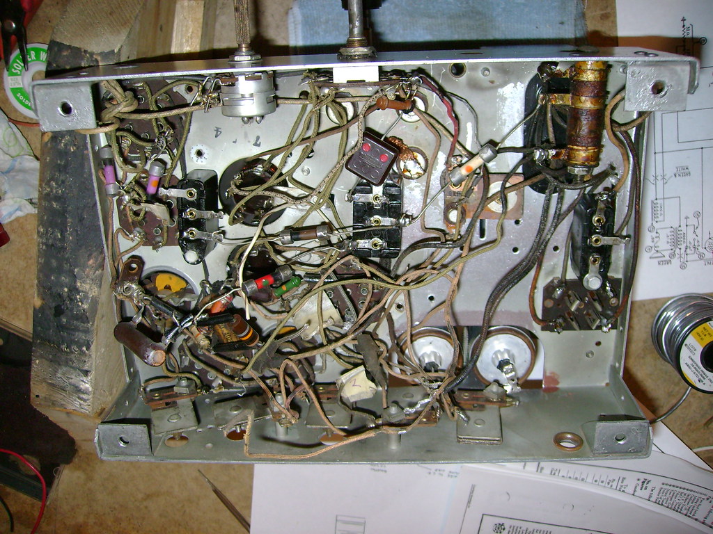 I did some hunting around online and found another that looks identical to mine. It's so nice to have an all original reference. 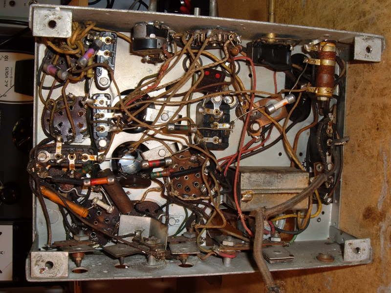
Last edited by bandersen; 04-26-2011 at 01:48 PM.
|
|
#83
04-29-2011, 09:51 PM
|
||||
|
||||
|
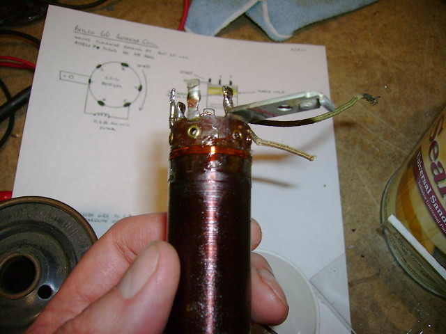
I'm in the homestretch (I hope). I reinstalled the tone control, cleaned the band switch and found a new volume/power switch.
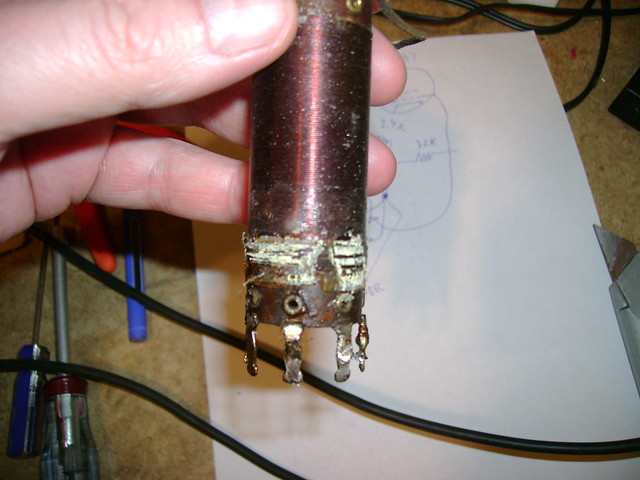
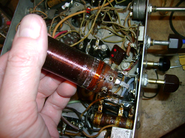
The one that came with the set was 1M but should be 350K. This 450K is the closest I could find and it has a really smooth action. If it works out well, I'll have to cut down the shaft. 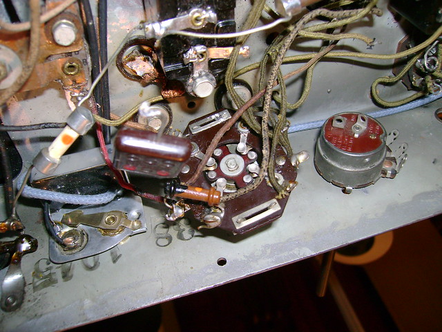 All 3 grid cap leads need to be replaced including this one on an IF can. 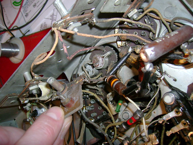 Here's the icky, gooey coil I found inside  It seems the old wax has bubbled over the years. Or maybe the coil form has outgassed ? 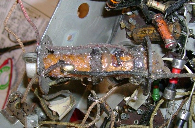 I wired in a new lead and hit it briefly with a heat gun on low to reflow the wax. 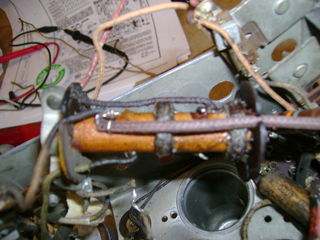 Almost done 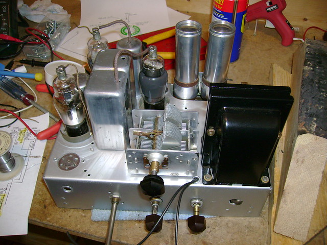
Last edited by bandersen; 04-29-2011 at 10:55 PM.
|
|
#84
05-05-2011, 09:20 PM
|
||||
|
||||
|
I found a few bad dogbone resistors and thought it would be fun to try replicating them using this technique.
My local JoAnn Fabrics had a sale on acrylic paint and I was able to get all 10 colors cheap I got the epoxy putty at Home Depot and used corn starch for the releasing agent. 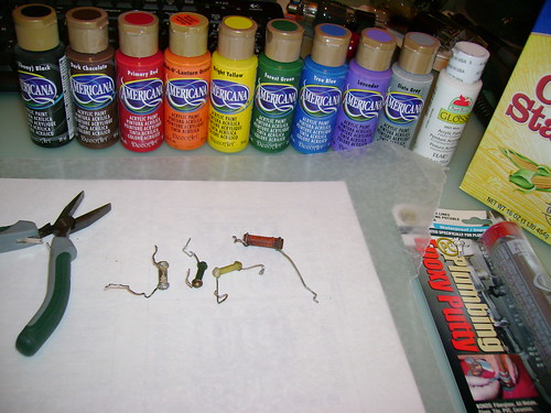 I messed up the first mold, but the next two turned out OK. 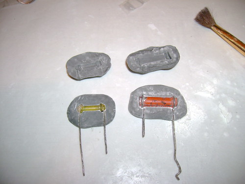 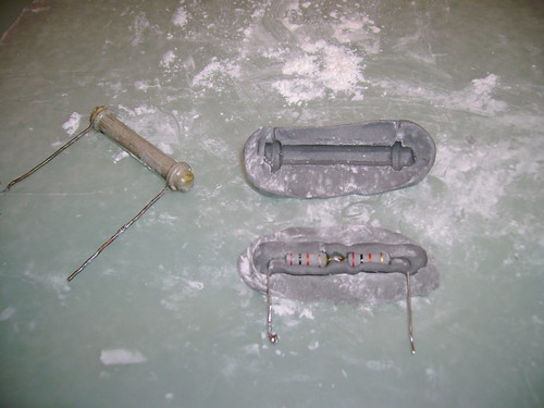 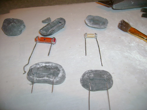 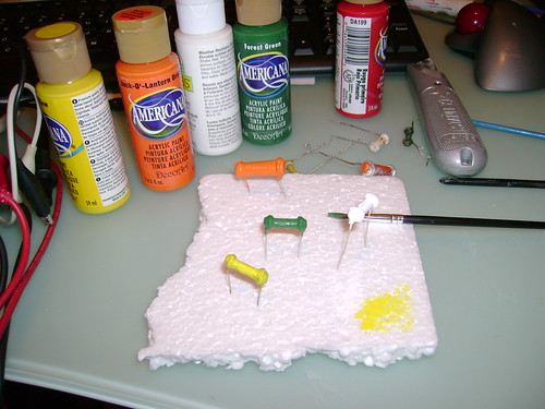 Here's the final result. Certainly not something I'd do on every project, but once you have the molds, it goes quickly. 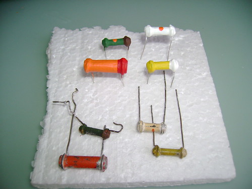
Last edited by bandersen; 05-08-2011 at 10:56 PM.
|
|
#85
05-05-2011, 09:37 PM
|
||||
|
||||
|
Here it is all wired up and ready for power. There are a couple modern resistors in series in the back right.
It had already been replaced with a modern resistor when I got the radio and I wasn't sure of the wattage. Once the radio is working, I'll see how hot it gets and create an appropriate dogbone. 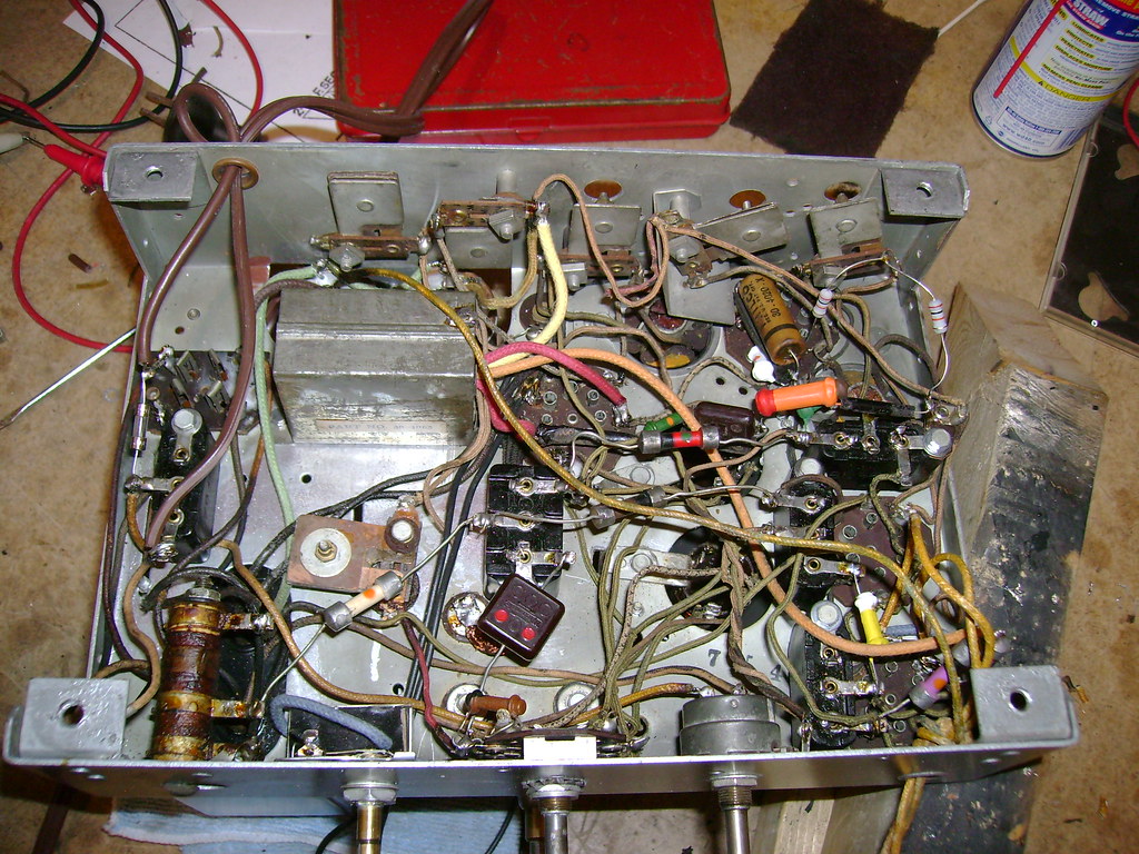 I added a 2A line fuse and a 60W bulb (Dim Bulb Tester) and turned it on. The B+ came up to about 500 then settled down to 250 - no smoke no flames Also no sound until I added an antenna. Once I did, I was treated to some familiar local AM stations  I removed the DBT now that I knew I didn't have any shorts. That got the B+ up to about 350v like it's supposed to be. AM is very strong and clear now, but still no SW. I loosely coupled an RF generator to the antenna input and scanned through the 1.5-4 MHZ band. Still nothing. I suspect the LO isn't running in SW mode. Time for some troubleshooting. 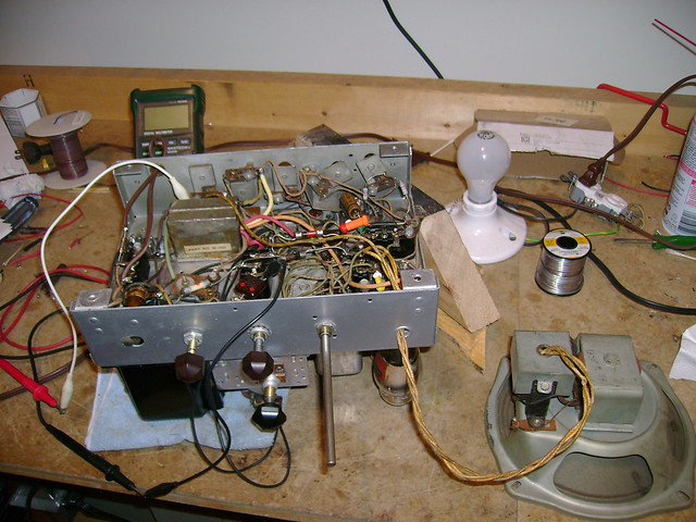 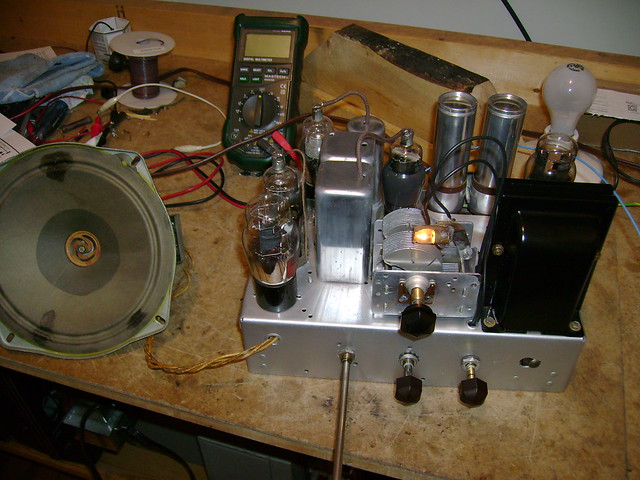
Last edited by bandersen; 05-06-2011 at 11:27 PM.
|
| Audiokarma |
|
#86
05-06-2011, 05:35 AM
|
||||
|
||||
|
Great dogbones! You could go into the business.
No LO on SW? Sometimes a tube doesn't like to oscillate up there, but another one will.
__________________
Reece Perfection is hard to reach with a screwdriver.
|
|
#87
05-06-2011, 12:58 PM
|
||||
|
||||
|
Quote:
I swapped in another 6A7, but have the same problem. The voltages on that tube are pretty close to what's expected. I'll do some more checking.
|
|
#88
05-07-2011, 08:25 PM
|
||||
|
||||
|
I got a great suggestion from the guy who's reconing my speaker to try reversing the tickler coil connections.
Worked like a charm  I have full coverage on the AM and SW bands now. Most likely someone rewound it the wrong way around. I have full coverage on the AM and SW bands now. Most likely someone rewound it the wrong way around.
|
|
#89
05-08-2011, 04:21 PM
|
||||
|
||||
|
I removed the oscillator coil and indeed the tickler was wound incorrectly. So I removed it and rewound it just like I did with the antenna coil.
  I then did an alignment by peaking each of the four IF trimmer caps at 460 kHZ. They really weren't off by much, but it helped a little.
|
|
#90
05-09-2011, 08:40 AM
|
||||
|
||||
|
That chassis looks so good that it's a shame to put it back into the case!.. Just leave it on the table and plug 'er in!..
Love the mold idea. !Did you make a vid of that process?  Buzz
__________________
______________________ Buzzsaaw Sunlitedreams.com
|
| Audiokarma |
 |
|
|


 Linear Mode

