
|
|
|
|
|
#1
 06-21-2019, 01:36 PM
|
||||
|
||||
|
Hallicrafters T-506 Late Production Set
Greetings, Gentlemen:
I recently acquired the Hallicrafters, and I'm replacing the selenium rectifier with a 1N4007 diode. It's been a long time since I've been on the bench, and I forgot how to tell the " + " end of the diode. Also, I hear you may need to install a resistor, and don't know what value to start with and where it goes. Thanks; Lee 

|
|
#2
06-21-2019, 03:40 PM
|
||||
|
||||
|
The end of the resistor body with the stripe is the + end. Start with about 50 ohms, at least 5 watts, and adjust from there. Sets with voltage doublers for the main B+ need a smaller resistor (typically 10-20 ohms, 10 watts) but I believe in this set that rectifier carries a smaller load. The added resistor simply goes in series with the diode, either before or after.
|
|
#3
06-21-2019, 04:35 PM
|
||||
|
||||
|
There are, obviously, two leads connected to the selenium rectifier. One to the positive marked end, and one to the negative. I take it the diode connects in similar fashion.
Does the 50 ohm resistor go between the negative lead to the diode or the positive? Thanks. PS: It's been awhile since I've done this.
|
|
#4
06-21-2019, 06:22 PM
|
|||
|
|||
|
Dumb as it seems, the '+' end of the selenium corresponds to the banded (cathode) end of the Si diode. The + sign simply means "the B plus comes out of here".
The resistor would connect "upstream" of the diode.
|
|
#5
06-21-2019, 07:07 PM
|
||||
|
||||
|
Quote:
 The end of the diode with the stripe is the + end. The added resistor goes on either side -- it doesn't matter which you choose.
|
| Audiokarma |
|
#6
06-21-2019, 07:38 PM
|
|||
|
|||
|
Which side doesn't matter, but conventionally it went on the input side of the diode.
|
|
#7
06-21-2019, 08:28 PM
|
||||
|
||||
|
Gentlemen ?!? Who come in ? (Grin) Lotsa luck fixin' the Halli... They are ALWAYS neat old sets...Me, I got an SX-28, S-36, SX-62B, SX-73 & a couple of others whose monikers escape me currently...Great mementos from the era when American radios & related stuff were second to NONE in the world...
__________________
Benevolent Despot
|
|
#8
06-22-2019, 10:40 AM
|
||||
|
||||
|
Quote:
|
|
#9
06-22-2019, 10:41 AM
|
||||
|
||||
|
Yup. Neat set. I've sent out the mahogany cabinet to be refinished. The front plate and bezels, etc I'll restore myself.
I want this one to come out primo. Waiting for the high voltage caps to come in...
|
|
#10
06-22-2019, 11:04 AM
|
||||
|
||||
|
Like a dummy, I only ordered two 470pF 15kV axial caps. I need four.
Can I substitute ceramic disc caps? Two are in the HV Cage, two underneath near the bleeder resistors. The parts list calls for 500pF 6kV.
|
| Audiokarma |
|
#11
06-22-2019, 11:20 AM
|
||||
|
||||
|
Another question: I hear the HV RF Coil is a soft spot on these TVs.
Should I: 1. Clean and bake it at 180 degrees? 2. Space the top lid by .25" 3. Add a muffin fan? Love to see a pic of the HV Cage with the fan installed. Thanks.
|
|
#12
06-22-2019, 11:39 AM
|
||||
|
||||
|
Quote:
That problem, however, is mainly with vertical deflection. In your set, those use much larger value capacitors like .01 uF (or I believe even .05 uF in the Hallicrafters). Your 470 pF caps are probably for horizontal deflection or HV filtering, which have less of a problem with this. What I found with ceramic capacitors is that if you simply use a significantly higher capacitance value than the original tubular capacitor, ceramic will work. So for example, if you see problems using 470 pF ceramic capacitors, then using something like 2000 pF (.002 uF) or more will probably work just fine. Maybe even .001 uF would do the trick. For some of my previous work on this subject, see: http://www.videokarma.org/showthread...=260749&page=2 I have a more complete write up of it somewhere else, but I can't find a link to it right now. Last edited by Tom Albrecht; 06-22-2019 at 12:16 PM.
|
|
#13
06-22-2019, 02:08 PM
|
||||
|
||||
|
Quote:
Maybe, but probably not. I did the steps I reported in the sequence listed. I started to have success with #3.
|
|
#14
06-23-2019, 10:33 AM
|
||||
|
||||
|
Over in the ARF the subject of the H.V. transformer has recently come up.
https://antiqueradios.com/forums/vie...p?f=3&t=359879
|
|
#15
06-25-2019, 01:15 AM
|
||||
|
||||
|
The way I always think about it is the stripe on the diode is the | from the schematic symbol ->|-
Which would also be the opposite of what Tom said, I believe he meant the + comes out of the stripe side. But the stripe side is the cathode (-) and the arrow side is the anode (+). So remember my mnemonic device so you don't get confused: in the symbol ->|- the arrow points in the conventional direction of electricity flow from + to - (not the actual direction in physics, which is backwards O_o [but don't think about that]) and the stripe on the diode is the vertical line |. 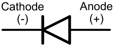 https://learn.sparkfun.com/tutorials...d-led-polarity Last edited by MadMan; 06-25-2019 at 01:21 AM.
|
| Audiokarma |
 |
|
|


 Hybrid Mode
