
|
|
|
#17
 05-14-2017, 09:05 PM
|
||||
|
||||
|
That'll work. I tend to do higher in value on paper caps rather than lower, not for any particular reason though. When the paper caps were new, they would have had tolerances no better than 20 percent, and in some cases closer to 50 percent. Either the 0.001 or the 0.0015 would work just fine.

|
|
#18
05-15-2017, 08:28 AM
|
||||
|
||||
|
I usually pick the closest value available so I can say it is in closer tolerance than it could have been.
A good habit to be in is to read the color coded values off the physically larger micas...Some are paper in mica's clothing. Usually there is a dot the color of which denotes dielectric type....If a mica has it's value textually printed on it then it is usually a paper cap.
__________________
Tom C. Zenith: The quality stays in EVEN after the name falls off! What I want. --> http://www.videokarma.org/showpost.p...62&postcount=4
|
|
#19
05-22-2017, 11:22 PM
|
|||
|
|||
|
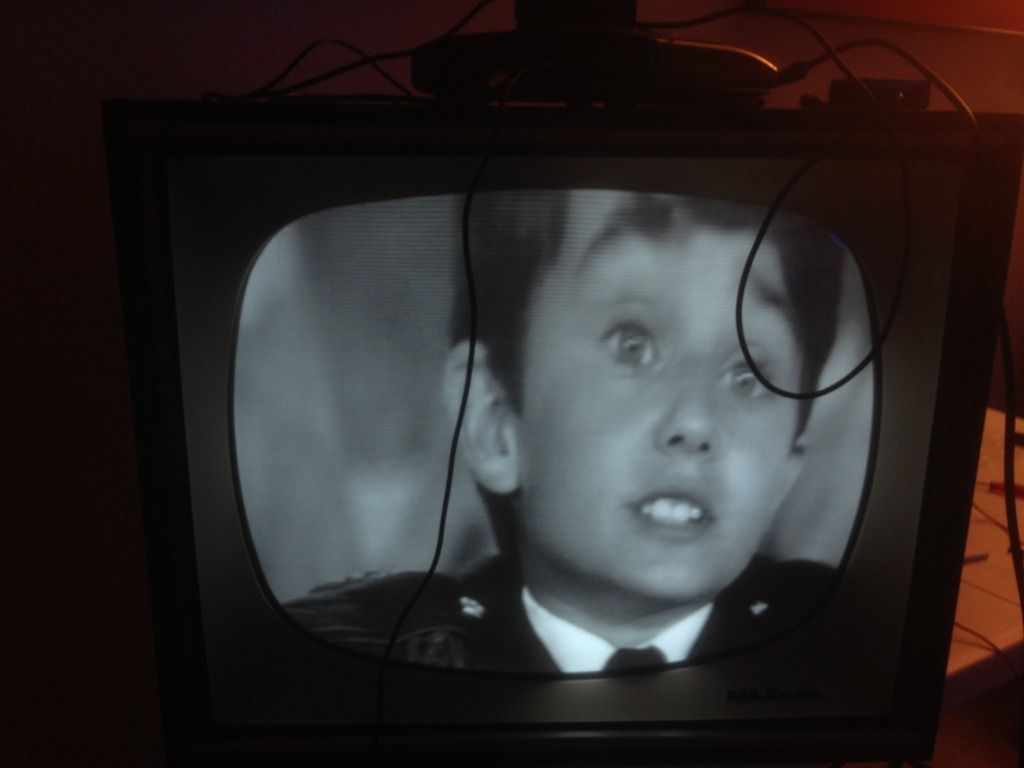
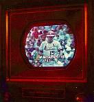
Got the horizontal oscillator board recapped! WE GOT HOLD. So far this is the best adjustment vertically I can get. Is there some combination of adjustments I'm missing or would a recap of the Vertical Oscillator board solve this issue? I have no problems getting a vertical hold.
|
|
#20
05-22-2017, 11:41 PM
|
||||
|
||||
|
I'd start by replacing all paper caps in the vertical circuits.
After doing that, I'd go to the service manual and look up the adjusters for height and vertical linearity. (Your pictures show a moderate problem with vertical linearity, where objects in the top of the screen are vertically stretched compared to the bottom area.) Note that these adjustments are somewhat interactive, meaning that adjusting linearity may affect the height a bit, and vice versa. You may need to go back and forth between the adjusters a few times to get the height and linearity just right. Looking pretty good, otherwise. Phil Nelson Phil's Old Radios http://antiqueradio.org/index.html Last edited by Phil Nelson; 05-23-2017 at 02:24 AM.
|
| Audiokarma |
|
#21
05-24-2017, 12:46 AM
|
|||
|
|||
|
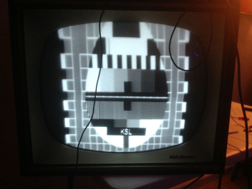
I recapped all but one paper capacitor in the vertical oscillation board. I wasn't able to source a .0037uf 1600V replacement. So far it seems to be working well! Better than I would expect from an almost 60 year old tv. It took a little centering adjustment as well to get it about right. There are a few issues I am noticing though. I have a buzz in the speaker depending on a combination of the fine tuning on the channel select and mainly from the contrast control. Along with the contrast control, it is causing issues where depending on what is displayed (usually a lot of white and then black) cause some wave distortion within the image. I am not sure if this is just the nature of the beast with these older tvs or if maybe I need to look into the contrast control and where that leads. Thank you all for the help! Its greatly appreciated.
|
|
#22
05-24-2017, 08:26 AM
|
||||
|
||||
|
A buzz in the audio when graphics are on the screen using a converter box is very common. The signal from the converter boxes are not as good as NTSC broadcast. I have my converter box feeding a Betamax and that combination works much better.
|
|
#23
05-25-2017, 09:20 PM
|
|||
|
|||
|
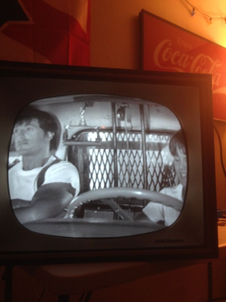
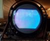
One thing of note that I can't quite figure out. It hates signals from a VCR. I run my hdmi->av into the vcr, its fine. If I play a tape however, it curves off at the top no matter what I sat my horizontal hold to. Its driving me nuts.
|
|
#24
05-25-2017, 10:53 PM
|
||||
|
||||
|
Quote:
Specifically, the VCR produces video that has a major timing error in the horizontal sync timing that happens in the vertical interval. This is when the VCR switches from one video tape head to the other that is mounted in the spinning drum the tape slides over when in play. Your TV is trying to quickly readjust itself to this poor horizontal sync, the result is the curving at the top of the picture. Newer TV sets were designed to be faster at readjusting themselves, but then be less noise immune and be more jittery in noisy reception.
__________________

|
|
#25
05-25-2017, 11:19 PM
|
|||
|
|||
|
Quote:
|
| Audiokarma |
|
#26
05-27-2017, 11:44 PM
|
||||
|
||||
|
Quote:
__________________
Tom C. Zenith: The quality stays in EVEN after the name falls off! What I want. --> http://www.videokarma.org/showpost.p...62&postcount=4
|
|
#27
05-31-2017, 02:28 AM
|
|||
|
|||
|
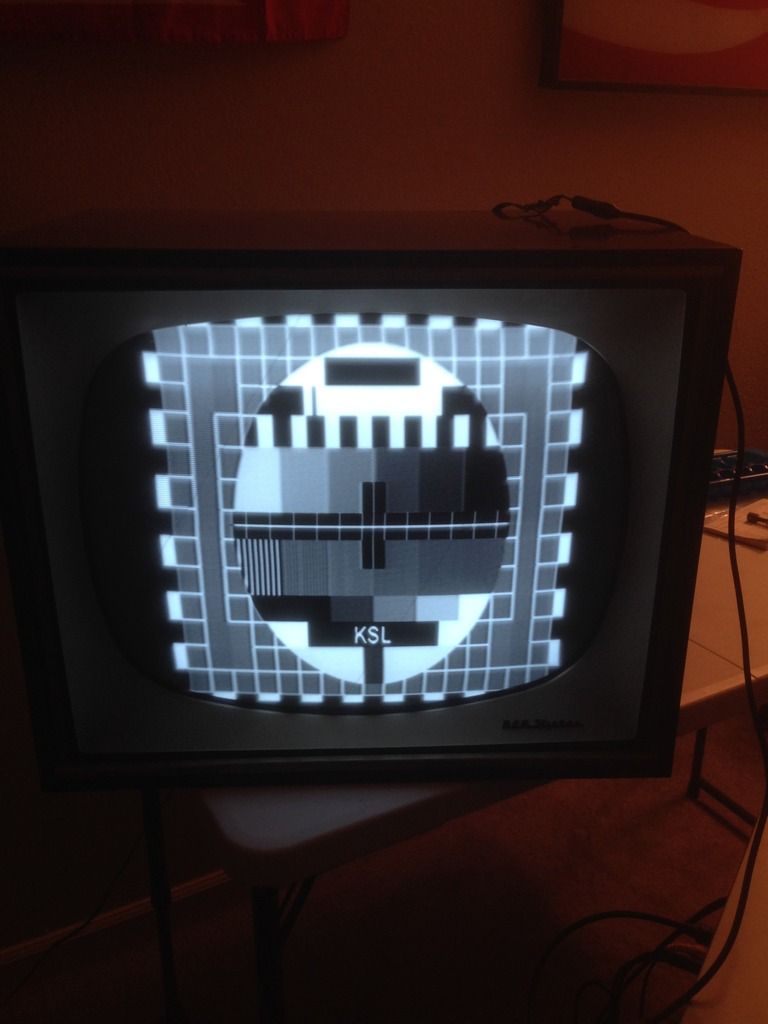
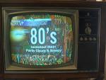
So, even running the signals straight from the hdmi to av converter to a rf modulator I get about an hour or so of play time before the waves start to appear. Adjusting some settings can fix things for awhile, but its no guarantee. What section would be causing this timing issue? I'd rather not shell out 250 bucks for an external TBC. If anything, I will probably just attempt a full recap of the paper capacitors in this TV as it has now become my semi daily driver.
|
|
#28
05-31-2017, 09:22 AM
|
||||
|
||||
|
By waviness do you mean to say that with a digital source after a while the top of the screen starts to flag wave in a similar manner to what it does with a VCR?
If so there are a few things I would do: Change the lytics in the power supply (so we know the B+ rails will be stable) if you have not already done so. Make sure all caps in the AGC, sync separator, Horizontal AFC, Horizontal oscillator, and H output have been changed, and make sure all resistors in those stages are within tolerance, also confirm the tubes in those stages are healthy. After doing that it may be wise to adjust the AGC after it has warmed up long enough for the sync to have gotten wavy. If the AGC is too high or too low sync may be affected. The AGC pot will have a low no signal zone where the picture fades to white, a good zone where sync is strong, and an overload zone where the pic will go negative and loose sync, and the audio may turn to buzz. Generally you turn up till you hit the overload region then back down just past the point where overload symptoms stop (some service lit for some sets specifies 1/4 turn below overload).
__________________
Tom C. Zenith: The quality stays in EVEN after the name falls off! What I want. --> http://www.videokarma.org/showpost.p...62&postcount=4
|
|
#29
05-31-2017, 10:57 AM
|
|||
|
|||
|
Quote:
|
|
#30
05-31-2017, 01:22 PM
|
|||
|
|||
|
Quote:
|
| Audiokarma |
 |
| Thread Tools | |
| Display Modes | |
|
|


 Linear Mode

