
|
|
|
|
|
#2
 02-18-2012, 12:27 AM
|
|||
|
|||
|
Oh. I meant gone from "stock" Meaning you cant purchase them anymore.
I guess i got mine while i could. shoulda got more. Here is a youtube video of mine when I built a breadboard based VFD controller that ran off the PC parallel port back in 2006 i think it was. http://www.youtube.com/watch?v=D_U-Fb5F-Ww Last edited by mbates14; 02-18-2012 at 12:37 AM. 
|
|
#6
02-19-2012, 04:15 AM
|
||||
|
||||
|
Quote:
philips-dcc900 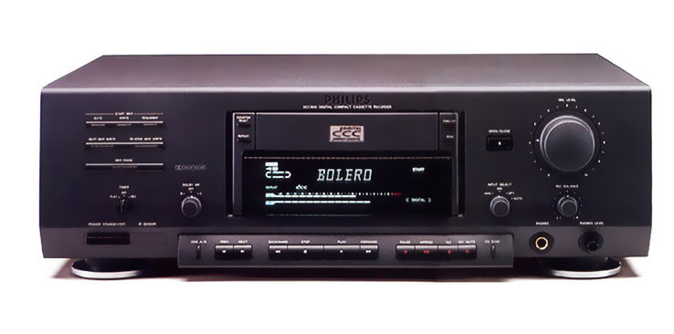 http://www.dutchaudioclassics.nl/phi..._dcc_recorder/ http://www.dutchaudioclassics.nl/phi..._dcc_recorder/  AND i haw dream to mod my VCR grundig vs220  with with  = =Last edited by Visual; 02-19-2012 at 05:22 AM.
|
|
#7
02-19-2012, 08:43 PM
|
|||
|
|||
|
Here are the few that I forgot:
the graphics VFD was a chip-on-glass one that I had gotten, no datasheet or pinout available, so i had to reverse engineer it myself. Although with the ghosting, I never did get too much further with it. My guess was it was a 3.3V VFD that I was driving with 5V.
|
|
#8
02-21-2012, 10:45 PM
|
||||
|
||||
|
http://www.audiokarma.org/forums/sho...d.php?t=420169
1987-8 GOLDEN AGES OF VFD HI-FI UNITS    i`m fanatically impression-ed of TV icons on VCR displays this is my tread- http://vintageelectronics.betamaxcol...cr-scans/page8 FOR COLOR SYSTEM MAC;NTSC 3.58;4.46;ME SECAM NM PAL TV-I,BG;BS\BROADCAST SATELLITE\ SOUND-NICAM;SAP;STEREO;DUAL TV FREQUENCY S-VPS;PDC;VDS;TXT ON THE SAME TIME ON VFD+LEVEL METER+S.A./SPECTRUM ANALIZER\+WEEKLY DAYS+DEW 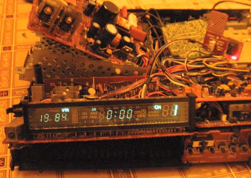 
Last edited by Visual; 02-27-2012 at 04:01 AM.
|
|
#9
07-22-2012, 06:14 PM
|
|||
|
|||
|
Busted?
Hiya guys, I'm neo, and new. Seems like you guys know a lot about VFDs and the workings of one. I have a VFD from my bike which has no display at all. Initially, I though it was a broken solder point (now fixed) which wasn't driving power to it. However, after some dismantling and getting to the display it self, I *think* the display is busted. Seems like there's "burn marks" inside the display.
Not sure if that's the case, so, need some help verifying it. From what I can gather after poking a multimeter at it, the VFD is getting power, it even makes this.. well, kinda discharging sound when the ignition is turned on. None of the solder points seem broken, cracked or otherwise unusable. On the PCB I see test points labelled 5v, Anode & GND. Probing with the tester reveals that there's no breaks in the circuitry. So, I'm guessing it's the tube. The two "burn marks" on the left of the tube in the picture is what's got me pretty sure.. well, sure as one can get anyway. Appreciate if you guys could help me confirm this. If it's busted, I'm pretty sure there's no way to fix it short of replacing the tube itself... So, yeah.. anything you guys got.. And thanks  
|
|
#10
07-22-2012, 09:29 PM
|
|||
|
|||
|
Nope, that tube is perfectly fine. If those "getters" were white, then I would worry. but they are not. they are normal color.
the VFD is fine, your problem is in the circuitry. your missing the filiment voltage, or anode voltage, or the VFD driver IC is bad. one of the 3. take your pick .
|
| Audiokarma |
|
#11
07-22-2012, 09:40 PM
|
||||
|
||||
|
I would suspect an electrolytic capacitor (or more) in a DC-DC converter circuit to run the VFD from 12V could well be at fault. Not too uncommon for capacitors to fail and displays go dim or out completely.
|
|
#12
07-23-2012, 01:09 PM
|
|||
|
|||
|
Thanks for the feedback guys. Yeah, I did some more reading on VFDs yesterday and apparently those getters aren't really burn marks, they're part of the manufacturing process (of course you guys would already know this, but new to me, heh)
It seems now I'll need to do a lot more probing. A whole lot really. The tube is mounted on a PCB which is connected to yet another PCB via 2 sockets, so tracing is gonna be a major pain. But at least now I have some ideas on what I should be looking for. Thanks again. Really appreciate it. I'll post again soon once done with all the probing.. -sigh- -K
|
|
#13
07-23-2012, 08:06 PM
|
||||
|
||||
|
But wait, there's more.
A VFD is a tube and can be used as a Triode. There's a www site showing it off. A video of an experiment: http://www.youtube.com/watch?v=aiszksJs9C8 I hope this will enrich your VFD interest.
__________________
Timeless Information for Retro-Tech Hobbyists and Hardware Hackers No Kowtow
|
|
#14
07-24-2012, 02:13 PM
|
|||
|
|||
|
Woah. That's just a lil bit above my level. Playing around with 120-180 volts.. hmmm.. Don't think I have anything up to that level yet. All I got for tinkering is a 12v DC transformer and a teeny variable 1.5-12v AC-DC.. I play around with automotive and some computer electronics which almost never goes over 12v.. Really interesting though. Mayhaps that dead VCR in the corner has some use later on..
Anyway, to the VFD at hand. Today after riding and parking in the dark, I noticed that the wires are indeed getting some current. They were faintly glowing.. Which means you guys were right, the VFD isn't dead. Something else is. Now just need to figure out what.. Gonna have to dismantle it again over the weekend or when I gots some free time.. Well, at least I know the re-soldered broken trace did do *something* p/s: the attached isn't actually my tube but it's doing the same thing 
|
|
#15
07-24-2012, 09:27 PM
|
||||
|
||||
|
A voltmeter can tell you what's going on there. Besides the filament voltage, most VFD take 35-40V to light up. If it is installed in equipment, the anode or grid segments may be 'scanned' with a voltage from the display driver IC, each one in turn being high or low, to light up the desired segments. Don't be surprised if the filament is at a negative DC potential and the anodes near GND. A scope can show you what is being pulsed or scanned.
About the higher voltages, at some time, if you work with them, it can only make you a better tech and wiser collector.
__________________
Timeless Information for Retro-Tech Hobbyists and Hardware Hackers No Kowtow
|
| Audiokarma |
 |
|
|


 Hybrid Mode
