
|
|
|
#181
 10-09-2013, 05:32 PM
|
||||
|
||||
|
Quote:
jr 
|
|
#182
10-09-2013, 09:51 PM
|
||||
|
||||
|
Quote:
I still think the dag is a wild goose chase for anything having to do with the jail bars (isn't that the one thing we are trying to fix here?). Need to stop shot-gunning and try to follow clues - there is a jail bar pattern in at least some of the CRT leads, and there are questions as to why some of the waveforms are fat (high frequency or low frequency superimposed?). Should be chasing down if those scope waveforms are valid and going from there.
|
|
#183
10-10-2013, 11:14 AM
|
||||
|
||||
|
Quote:
__________________
Pioneer SX-1080, Pioneer PL-115D, Pioneer CT-F9191, Pioneer RG-1, Wollensak 8050A, Akai 4000DS MkII, Pioneer CS-05 & Polk 1.2TL Denon 5803A, Pioneer DVL-700, Pioneer CT-W603RS, Toshiba HD-A3, D-Link DSM-520, Dish VIP-722, Polk 1.2TL, CSi5, LS/fx, RT-800 and PSW-650
|
|
#184
10-12-2013, 11:39 AM
|
||||
|
||||
|
Never mind. I missed a couple of points of connection, so I'll have to start over. I thought I was able to delete posts, but I don't see how.
__________________
Pioneer SX-1080, Pioneer PL-115D, Pioneer CT-F9191, Pioneer RG-1, Wollensak 8050A, Akai 4000DS MkII, Pioneer CS-05 & Polk 1.2TL Denon 5803A, Pioneer DVL-700, Pioneer CT-W603RS, Toshiba HD-A3, D-Link DSM-520, Dish VIP-722, Polk 1.2TL, CSi5, LS/fx, RT-800 and PSW-650 Last edited by TinCanAlley; 10-12-2013 at 11:47 AM.
|
|
#185
10-13-2013, 10:59 PM
|
||||
|
||||
|
Okay, spent the better part of today looking into why the setup doesn't produce a line. This is what I found out, but not why or how to fix.....
The G1 voltage controls brightness and the higher the voltage, the dimmer the output. The voltage should be around 142V for normal and actually measures out around 147 - 150V. That's not too bad. It's when the setup mode is entered that things change. The voltage of the G1s goes up to 190V and that must be why I can't see the lines when adjusting the G2. 190V is making it too dim to see. Now why the voltage goes up that high is beyond me. I looked over the schematics and see an 18K and a 1.8K resistor on the setup side of the switch and am not sure if one of those (or a combination of both) could account for the voltage difference.
__________________
Pioneer SX-1080, Pioneer PL-115D, Pioneer CT-F9191, Pioneer RG-1, Wollensak 8050A, Akai 4000DS MkII, Pioneer CS-05 & Polk 1.2TL Denon 5803A, Pioneer DVL-700, Pioneer CT-W603RS, Toshiba HD-A3, D-Link DSM-520, Dish VIP-722, Polk 1.2TL, CSi5, LS/fx, RT-800 and PSW-650
|
| Audiokarma |
|
#186
10-14-2013, 03:30 PM
|
||||
|
||||
|
Quote:
G1 voltage higher = more brightness. Cathode (K) voltage higher = less brightness. It's mainly the difference between cathode and G1 that controls beam current, so you have to measure both to figure out what's happening. These voltages *should* change to a predetermined value when you go to the setup mode, so that you can set the G2s for proper cutoff; then when you go to normal, the signals on the cathodes and G1's will produce the right colors.
|
|
#187
10-14-2013, 04:44 PM
|
||||
|
||||
|
Quote:
"The control grid (G1) controls the brightness of the CRT. It is generally placed directly on top of the cathode. If there is no voltage on G1, the electrons can flow freely from the cathode. If there is some negative voltage on G1, the electrons from the cathode are repelled somewhat, and the screen appears darker. The greater the voltage on G1, the darker the screen becomes, because more electrons reaching the screen equals a brighter image, and less electrons hitting the screen equals less brightness." I'm attaching the CRT section of the schematic. If I have the G1 information incorrect, I need to know. My understanding is pins 2, 11 and 6 are the G1s. I'm also attaching a pic of a chart from a CRT tester manual.
__________________
Pioneer SX-1080, Pioneer PL-115D, Pioneer CT-F9191, Pioneer RG-1, Wollensak 8050A, Akai 4000DS MkII, Pioneer CS-05 & Polk 1.2TL Denon 5803A, Pioneer DVL-700, Pioneer CT-W603RS, Toshiba HD-A3, D-Link DSM-520, Dish VIP-722, Polk 1.2TL, CSi5, LS/fx, RT-800 and PSW-650 Last edited by TinCanAlley; 10-14-2013 at 04:47 PM.
|
|
#188
10-15-2013, 12:14 PM
|
||||
|
||||
|
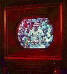
Just made a discovery. As most will recall, I can't get the setup line to show. That was until today. I managed to get the line to show, but under conditions outside of the normal setup procedure.
I set the switch into setup mode and there was no line. I then pulled the red tap off, completely and a bright red line showed up. I then did the same to the blue and green and got a bright whitish line in the center of the screen. Now outside of setup, the screen is way too dark to be useful. I then checked the voltage on the blue video output driver (yellow/blue wire on crt #11). It is 188 - 190V in setup with the tap in any of the HI, MED or Lo position. However, when I remove the tap connection it drops down to 132V and that when a very bright blue line shows up. The Sams says to do this with the taps on "HI", so something must be off to keep the line from showing up with the haps connected. So, does this new information give anyone any ideas as to what the problem might be? Is there something I should be measuring while the taps are disconnected? The collectors of the video output transistors?
__________________
Pioneer SX-1080, Pioneer PL-115D, Pioneer CT-F9191, Pioneer RG-1, Wollensak 8050A, Akai 4000DS MkII, Pioneer CS-05 & Polk 1.2TL Denon 5803A, Pioneer DVL-700, Pioneer CT-W603RS, Toshiba HD-A3, D-Link DSM-520, Dish VIP-722, Polk 1.2TL, CSi5, LS/fx, RT-800 and PSW-650 Last edited by TinCanAlley; 10-15-2013 at 12:23 PM.
|
|
#189
10-15-2013, 01:14 PM
|
||||
|
||||
|
Okay, another update and question.
Since finding out that disconnecting the screen tap wires from the taps allowed the setup line to appear, I decided to check voltages. I found something I don't understand, and therefore, don't know if it's normal. I am attaching a pic from the schematics for the video outputs and screen taps. In it you'll notice that the screen taps get voltage from the collector and the 240V boost through a series of resistors. Those are the supply connections. Then there is the tap wire that you move from tap to tap. That wire receives the voltage and it is connected with a resistor to the CRT socket. That lead has no power indicated on the schematics unless it's connected to one of the taps (hi, med or lo). However, when I disconnect the lead and check it, it has 133V on it. If I disconnect the CRT socket and run the set, the lead has 0V. It's the same for all three colors. Is that normal? Should there be voltage on it from the CRT side? On all three colors? Maybe I'm not fully understanding how this section is designed to work.
__________________
Pioneer SX-1080, Pioneer PL-115D, Pioneer CT-F9191, Pioneer RG-1, Wollensak 8050A, Akai 4000DS MkII, Pioneer CS-05 & Polk 1.2TL Denon 5803A, Pioneer DVL-700, Pioneer CT-W603RS, Toshiba HD-A3, D-Link DSM-520, Dish VIP-722, Polk 1.2TL, CSi5, LS/fx, RT-800 and PSW-650
|
|
#190
10-15-2013, 02:17 PM
|
||||
|
||||
|
Quote:
jr
|
| Audiokarma |
|
#191
10-16-2013, 05:02 PM
|
||||
|
||||
|
Quote:
|
|
#192
11-06-2013, 11:23 PM
|
|||
|
|||
|
Ringing,assuming the damping resistor across the line linearity coil is ok,is often caused by the bypass cap in the video output stages being o/c,value usually 10-33uf 250v,make sure,as with everything you don't use chinese sxxt as replacements
|
 |
| Thread Tools | |
| Display Modes | |
|
|


 Linear Mode

