
|
|
|
#16
 08-07-2023, 05:52 PM
|
||||
|
||||
|
Word of warning. The AGC delay (center of photo), sound buzz and channel LO adjustments are all very close to the metal CRT cone. Take great care when adjusting them with the TV powered up.
I got a bit careless and was bitten on the knuckle by about 9,000 volts. No damage done at that low current, but it will wake you up. 

|
|
#17
08-08-2023, 03:49 PM
|
||||
|
||||
|
I picked up a copy of the Sams Photofact and starting going through the resistance chart.
Found a problem in the very first tube. Hidden down inside the tuner I found a fried 1K resistor that feeds the plate and screen of the 6BJ6 RF amp tube. It was only measuring a couple 100 ohms in circuit and fell apart when I removed it. I really thought I had it but unfortunately, replacing it made no difference at all. Might even be a little worse now. I'll keep digging. 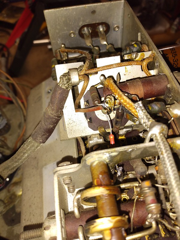 
|
|
#18
08-09-2023, 05:51 AM
|
||||
|
||||
|
Quote:
Im wondering if that was a factor in the downfall of metal CRTs - servicemen hated them. Actually, the metal CRT was a weird idea anyway. I dont know why it came about in the first place. Maybe someone at RCA was bored one day
|
|
#19
08-09-2023, 09:00 AM
|
|||
|
|||
|
Maybe it was the push for bigger screen size before the all-glass technology was mature enuff for it.

|
|
#20
08-09-2023, 09:09 AM
|
||||
|
||||
|
RCA spent 13 years developing the metal cone CRT. Reduce cost, reduce weight, increased screen size.
You can read all about the introduction of the 16AP4 here: https://worldradiohistory.com/hd2/ID...-Page-0006.pdf Another great article here: https://worldradiohistory.com/hd2/ID...-Page-0085.pdf and application notes: https://www.one-electron.com/Archive...of%2016AP4.pdf
|
| Audiokarma |
|
#21
08-09-2023, 09:58 PM
|
||||
|
||||
|
Went over the tuner again check all the voltages, contacts, etc - found no issues.
Found an open peaking coil on the video amp. Bridging it made no difference  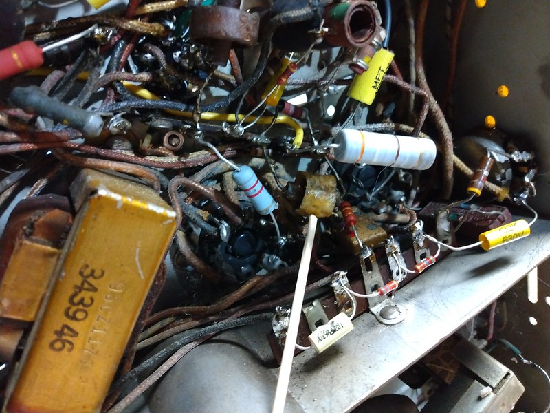 Just picked up this TeleMatic Tuner-Mate KT 730. It has a 44MHz IF you can inject into a TV to substitute for the tuner. Maybe it will help? Really it shouldn't be any different than the signal injection I already tried, but it's fun to play around with vintage gear. Seems to me the problem has to be in the tuner or early in the IF. The video signal at the CRT is fairly strong but the signal to noise ratio is terrible. AGC voltage is also very high. For example, the grid voltage on the tuner RF tube should be around -0.5 volts, but I have positive 0.5 volts. The signal is just not getting through cleanly somewhere. 
Last edited by bandersen; 08-09-2023 at 10:04 PM.
|
|
#22
08-09-2023, 11:15 PM
|
||||
|
||||
|
That positive grid bias may be a clue.
1) Have you tested the tuner and IF tubes? 2) How about injecting a negative voltage and seeing if the picture clears up. If it does, then you need to look for a fault in the circuit that supplies that bias voltage.
|
|
#23
08-10-2023, 09:52 AM
|
||||
|
||||
|
I've tested and swapped out every tube several times. If I inject a negative voltage the image fades away. Seems the AGC is asking for as much gain as possible due to a weak signal coming through the IF.
Something else odd I noticed is scoring on the inside of the tuner cover. The contact fingers are slightly worn down as a result. This thing is really solid made with thick, formed sheet metal with no room for adjustment. I get the impression it's been this way since it was made. Anyone with porthole experience see something like this before? 
|
|
#24
08-10-2023, 10:37 AM
|
||||
|
||||
|
What happens to the picture when you adjust the AGC delay?
|
|
#25
08-10-2023, 10:39 AM
|
||||
|
||||
|
The gain varies. I have it maxed out for the screen shots I took.
|
| Audiokarma |
|
#26
08-10-2023, 11:00 AM
|
||||
|
||||
|
I don't think I have seen any contact scraping on the tuner cover before on my porthole sets doing tuner cleans.
You may want to look for anything mechanically out of whack causing the scraping.
__________________
Tom C. Zenith: The quality stays in EVEN after the name falls off! What I want. --> http://www.videokarma.org/showpost.p...62&postcount=4
|
|
#27
08-10-2023, 11:49 AM
|
||||
|
||||
|
Quote:
Hypothetically, the AGC delay is supposed to keep the RF AGC from operating for input signals below a certain level. So, for example, going from zero to 1 mV RF input, the RF stage should have constant max gain while the IF AGC voltage varies the IF gain from maximum to some reduction as required to get normal detected video level. Then above the delay set point (1 mV in this example) the RF AGC starts to vary to reduce gain in the tuner as well as in the IF. Can you put two voltmeters on the RF and IF AGC voltages and supply a variable level RF input to see if there actually is any delay action? Another thought: could there could be a bad RF connection at the tuner input?
|
|
#28
08-10-2023, 03:02 PM
|
||||
|
||||
|
The RF and first 3 IF stages use the same AGC signal. This design used an AGC circuit gated by the horizontal sync pulse. I believe the delay determines how long the AGC tube conducts after the start of the sync pulse.
You can get the full Zenith service manual from the ETF here: https://www.earlytelevision.org/pdf/...anual_tv-5.pdf
|
|
#29
08-10-2023, 05:22 PM
|
||||
|
||||
|
Thanks. I downloaded the manual.
|
|
#30
08-10-2023, 05:37 PM
|
||||
|
||||
|
The AGC Delay control is a variable voltage divider between 150 volt supply and ground, connected to the AGC amp cathode. It looks to me like it mainly sets the threshold of IF output level for the AGC amp to conduct. It doesn't conduct "until" the IF output reaches a set level. So, it's an AGC control - forget the "delay" word.
Afraid this gives no hint of what the problem is.
|
| Audiokarma |
 |
|
|


 Linear Mode

