
|
|
|
#16
 02-01-2018, 06:12 PM
|
||||
|
||||
|
Quote:
__________________
Tom C. Zenith: The quality stays in EVEN after the name falls off! What I want. --> http://www.videokarma.org/showpost.p...62&postcount=4 
|
|
#17
02-02-2018, 02:25 AM
|
||||
|
||||
|
Done That Already
Removing the CRT with the accoutrements attached was simple. Aquadag coating (or whatever) looks intact.
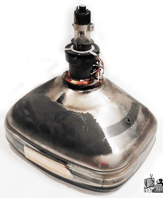 Cleaned up the chassis a bit, and now I'm checking continuities through all coils. The yoke checks out OK. 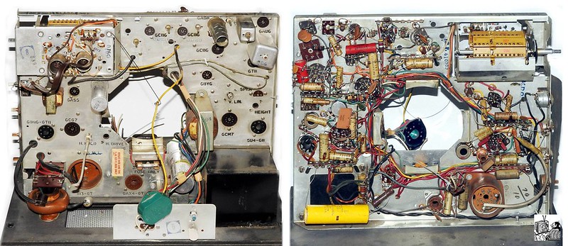
__________________
Winky Dink Damn the patina, Full speed ahead!
|
|
#18
02-04-2018, 06:03 PM
|
||||
|
||||
|
A Little More Help, Please
Below is a photo of the wiring of one of the 'lytics. It appears to be factory-wired, but I can't reconcile it with the Sams schematic, parts list, and the info stamped on the can.
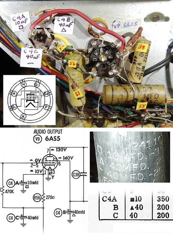 So, please tell me that I'm reading it wrong or, if the schematic and the wiring disagree, which I should do--follow the schematic or duplicate what's already there. Thanks, Henry.
__________________
Winky Dink Damn the patina, Full speed ahead!
|
|
#19
02-04-2018, 06:20 PM
|
|||
|
|||
|
Quote:
The 6AS5 audio output tube is used a voltage divider as well. The voltages shown are way off. The voltage on the cathode should be at least 100 volts or more. Just wire it the way you find it! It worked before! 
|
|
#20
02-04-2018, 07:52 PM
|
||||
|
||||
|
Thank you. I'll proceed as advised and I'll keep in mind the voltage discrepancies when I get there.
__________________
Winky Dink Damn the patina, Full speed ahead!
|
| Audiokarma |
|
#21
02-05-2018, 09:58 AM
|
|||
|
|||
|
Quote:
|
|
#23
02-06-2018, 09:42 AM
|
|||
|
|||
|
Quote:
|
|
#24
02-19-2018, 11:46 PM
|
||||
|
||||
|
Moving Forward
Regarding the Sams 6AS5 schematic error, I got the Rider schematic, and it shows the correct wiring and voltages. The voltage shown on the Sams schematic are measured from a 110 volt line, so that explains why they're all about 110 volts too low.
 I'll be ready to power up the set in a few days. My concern is how to set up the CRT off the chassis. I can't imagine trying to check voltages with the CRT mounted on the chassis. I made a connector for the yoke wiring from an octal base and socket. It has plenty of extra length, but it'll be easy to shorten it. The solder connections are insulated with 1/4-inch irrigation tubing which fits snugly but slides on and off easily. 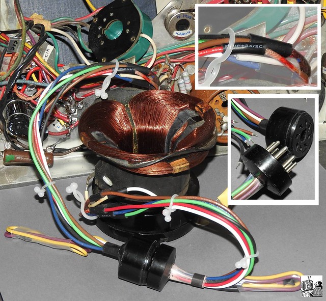 The limiting factor is the six-inch high voltage line. I have some cable rated 40 kilovolts. The CRT is 15 kilovolts. Is it feasible and safe to splice 14 inches of that to extend the original 6-inch cable?
__________________
Winky Dink Damn the patina, Full speed ahead!
|
|
#25
02-21-2018, 12:10 AM
|
||||
|
||||
|
Temporarily extending the EHT lead won't be a problem. Just insulate it well. In Aus we had a set with a similar layout (Thorn Atlas) and that's how I used to work on them. You will also need to arrange a connection from the aquadag to the chassis. By the way I noticed the exhaust tip on one of the tubes in the tuner has been knocked off and the getter is white.
|
| Audiokarma |
|
#27
02-22-2018, 06:54 AM
|
||||
|
||||
|
Quote:
|
|
#28
02-22-2018, 04:43 PM
|
||||
|
||||
|
I have a Nikon Coolpix P610. My photography secret is having no particular skill, but abundant time and patience. I may take 10 or 20 exposures for a single shot, varying the angle and lighting (flash; incandescent; LED; flash plus incandescent; etc.) Then I manipulate the jpegs (color saturation, intensity, gamma, brightness, etc.) and remove whatever I don't want in the picture--such as distracting background. Then if I don't have what I want, I start over.
__________________
Winky Dink Damn the patina, Full speed ahead!
|
|
#29
02-22-2018, 05:26 PM
|
||||
|
||||
|
Strange Little Capacitors
Thanks for the advice on managing the CRT, especially the reminder to chassis-ground the aquadag. I'll also have to make a simple wooden cradle for the CRT to hold it steady and keep it from rocking back onto the neck.
I disassembled the tuner--that is, I took out the drum to access the caps and resistors. I could have skipped this step because even though some resistors are slightly outside the specs, I'm not going to replace them. What's new to me is the capacitors used for wires going through the metal chassis into the tuner. I have a vague notion that the current passing the metal wall creates mysterious electromagnetic radiation which is suppressed by the mysterious capacitors. I took one apart, and I still can't see how they're constructed. 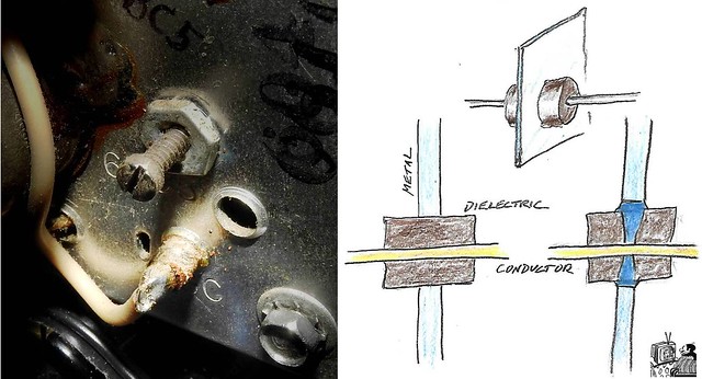 I'm asking about this because I need to know how to replace the one I destroyed--or it I need to replace it at all. Also, while I'm here, I've been meaning to ask about this for years--what kind of capacitor is this little guy. It's 4.7pF (I wrote "27" because it's C27). My tester is only reliable down to about 10pF, so I never know what to do with them.  Thanks for the help, Henry.
__________________
Winky Dink Damn the patina, Full speed ahead!
|
|
#30
02-22-2018, 05:49 PM
|
||||
|
||||
|
TIP: Unless you are good at TV sweep alignment NEVER touch pf rated caps or the feedthrough caps on the tuner (unless you have a darn good reason to suspect they are bad)...Doing so can screw up the alignment.
__________________
Tom C. Zenith: The quality stays in EVEN after the name falls off! What I want. --> http://www.videokarma.org/showpost.p...62&postcount=4
|
| Audiokarma |
 |
|
|


 Linear Mode

