
|
|
|
|
|
#1
 04-08-2015, 12:54 PM
|
||||
|
||||
|
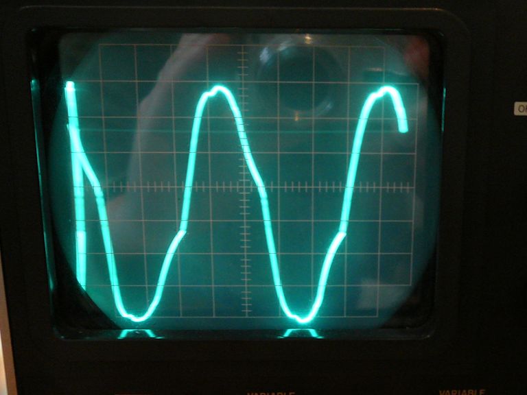
Hey, I just remembered that my Sencore VA62A video analyzer can supply a 3.58-mc drive signal. I hauled it off the shelf and fired it up. My scope has a hard time locking on the signal, but there seems to be a waveform of sorts.
 I disconnected the crystal and connected the analyzer's 3.58-mc drive output to pin 6 (grid) of the oscillator tube. After adjusting the generator's output voltage, I began to see rolling colors moving upward on the screen, similar to what I've seen before when the color sync was messed up on my CT-100.  I tried adjusting the reactance coil (L127 in the RCA manual) through its entire range, but this had no effect on the rolling, which never changed speed. And I still don't see normal colors, only rolling patterns against the same green-blue bar background. Turning the TV's Color control had the same effect as before: no change in the colors, and the image will just extinguish if you turn Color down far enough. The symptoms are the same whether I send the color-bar signal from my pattern generator through the TV's tuner and (lousy) video IF sections, or inject video directly at the 1st video amp. I'm going to go back and repeat the procedure outlined on page 22 of the RCA manual, disconnecting the bandpass amplifier, trying to adjust T115, and so on. Phil Nelson Last edited by Phil Nelson; 04-08-2015 at 03:25 PM. 
|
|
#2
04-08-2015, 02:21 PM
|
||||
|
||||
|
Its obviously best to use an accurate 3.58, but even the cheesiest signal generator will get close enough to test throughput ... just not phase.
|
|
#3
04-09-2015, 11:36 PM
|
||||
|
||||
|
Quote:
 In that photo, the scope was connected to terminal F on T115. By turning the bottom adjuster of T115, I could increase the amplitude up to a point, beyond which it fell off again. When I moved the probe to terminal D, the waveform looked about the same, although I didn't try the top adjuster. None of which helps me figure out why the oscillator doesn't oscillate, but I'm taking it as evidence that T115 is operational, anyhow. I had to move the adjuster quite a long way from its original position to find the peak, but perhaps that isn't surprising, given that many of the components attached to T115 have been replaced. Phil Nelson
|
|
#4
04-10-2015, 12:50 AM
|
|||
|
|||
|
By sheer elimination, it begins to look like maybe the resonance point of the L42/C213 tank circuit is too far off from 3.58 to allow oscillation.
Do you have a signal genny that's reasonably well calibrated, and can be manually swept thru 3.58mc? If so, you might try sweeping the tank and watch for the resonant point on the scope. (But first disconnect the tank from the tube cathode and C209. Connect the genny and scope to the top of the tank.)
|
|
#5
04-08-2015, 06:57 AM
|
||||
|
||||
|
How about those resistors R248, 249, and 250???
R250 should be ok since you got your plate voltage.... Same with primary on T115. Are the voltages on pin 2, and 3 correct....? .
__________________
Yes you can call me "Squirrel boy"
|
| Audiokarma |
|
#7
04-08-2015, 08:23 PM
|
|||
|
|||
|
Quote:
Since L42 goes to pin 3 (cathode), pin 3 should be showing 10.6 ohms to ground. Were you measuring the coil with one end disconnected? If so, could there be a short inside the socket from pin 3 to ground? Last edited by old_coot88; 04-08-2015 at 08:40 PM.
|
|
#8
04-08-2015, 08:58 PM
|
||||
|
||||
|
Sorry, I've been flipping back & forth between the Sams & RCA schematics and jumbled some numbers.
The 10.8 ohms reading was across L127, the reactance coil. That is with everything connected on that coil. Resistance from pin 3 to ground is 2.1 ohms. That's across L42 with everything connected. The RCA manual has no resistance chart, but for what it's worth, Sams says resistance at pin 3 should be .4 ohms, where I now measure 2.1 ohms. I did some checking of T115, the CW transformer. Resistance across the primary (from B to E) is 7.0 ohms. Resistance from F to A (F to ground) is .1 ohms. Resistance from D to C (D to ground) is .1 ohms. This is with everything connected to T115. Someone has worked in this area before. C202, the 120-pf cap on pin 6, looked like a replacement, attached hook-and-loop style to a stub left on the terminal. R246, 22K, is another obvious hook-and-loop replacement. The crystal may also have been replaced; one of its leads was much too long, and with strange bends -- not neatly dressed as you'd expect from the factory. Phil Nelson Last edited by Phil Nelson; 04-08-2015 at 11:16 PM.
|
|
#9
04-09-2015, 12:46 PM
|
||||
|
||||
|
Only the secondaries are tuned, not sure why the schematic shows it is. Never caught that before, but it doesn't matter. Keep looking for bad parts, I'm sure you'll see something obvious sooner or later.
__________________
Evolution... 
|
|
#10
04-09-2015, 06:17 PM
|
||||
|
||||
|
My guess is that the problem is in the cathode and grid area of the 3.58 MHz oscillator. If possible measure the component values, especially the cathode inductor L42 , its capacitor C213, the 4 pf feedback cap C209, the crystal and its resistor. Or maybe some conductive goo on the tube socket pins? My 21CT55 oscillator cathode tuned coil had been mis-adjusted and caused the oscillator to stop often.
|
| Audiokarma |
|
#11
04-09-2015, 06:30 PM
|
||||
|
||||
|
I will keep plugging along. On the positive side, I tried dtvmcdonald's trick to test the crystals, and they all look good, including the one that was installed in the set. Each of them shows a distinct peak on the scope at around 3.58mc.
I replaced a couple more components around that tube, without making any improvement. This updated schematic shows the 5 caps and resistors replaced there.  None of those components was grievously out of spec -- well, R249 measured 54K instead of 47K -- but at least I can cross those off the list of possible suspects. Of the remaining components connected immediately to that tube, we also can eliminate the crystal, which tested OK, and resistor R248, which measures a hair over 47K. Edit: I just saw the reply from Zenith6S321. One thing I haven't tried yet is disconnecting L42 to measure it. I can try that later on, along with giving the socket another good hard cleaning. Phil Nelson
|
|
#12
04-10-2015, 10:17 AM
|
||||
|
||||
|
I simulated the circuit. The cathode tank needs to resonate
a bit below 3.58 MHz. Apparently its doing some phase shifting. It seems non critical, 2.5 to 3.2 seems to work.
|
|
#13
04-10-2015, 12:04 PM
|
||||
|
||||
|
It's difficult to sneak a soldering iron into the place where those two components connect to the tube, much less other tools. In the event that I fry or mangle L42 in the course of experiments, what's a good replacement -- something like this?
http://www.mouser.com/ProductDetail/...tRRhUO5QN1Y%3d Phil Nelson
|
|
#14
04-10-2015, 01:40 PM
|
|||
|
|||
|
I would say go for it. The extreme disparity in DC resistance is no doubt due to its having a ferrite core vs. the original's air core (hence fewer turns of wire).
|
|
#15
04-11-2015, 02:08 AM
|
||||
|
||||
|
I disconnected C213 and L42 from the oscillator tube, and when I lifted up L42, it looked scorchy:
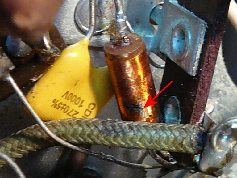 There was a layer of melted varnish sticking it to the green wire below. (I scraped that off before taking the photo.) The coil is missing varnish in the area where they touched, and some of its wires look burned black. It has continuity, measuring 2.6 ohms resistance. Not having another coil to compare, I have no idea what that figure means; if it has shorted coils, I suppose it could show continuity but have the wrong inductance. Quote:
It's possible I had things set up wrong. What I did was to connect C213 and L42 in parallel (but disconnected from the tube). Then I connected the sig gen at one end of this pair and the scope at the other end. I slowly changed the frequency of the sig gen and watched for a peak of some kind. Again, with my crude old generator, it's not possible to s-l-o-w-l-y vary the frequency around that exact point, or even hold it precisely, except at whatever frequency it flops to when you let go of the knob. Phil Nelson
|
| Audiokarma |
 |
|
|


 Hybrid Mode
